Cleaver having a crush-forged crank

A technology of protruding parts and machetes, which is applied in the field of machetes to achieve comfortable operation and improve stability

Active Publication Date: 2009-08-19
ZWILLING J A HENCKELS
View PDF2 Cites 1 Cited by
  • Summary
  • Abstract
  • Description
  • Claims
  • Application Information

AI Technical Summary

Problems solved by technology

Uncomfortable pressure points can thus form on the fingers, since the blade face and / or the blade face on the handle side do not have a shape that takes into account the anatomy of the finger

Method used


Image

  • Cleaver having a crush-forged crank
  • Cleaver having a crush-forged crank
  • Cleaver having a crush-forged crank

Examples


Embodiment Construction

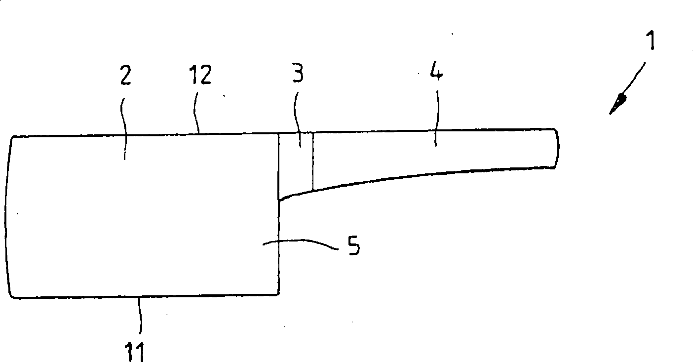
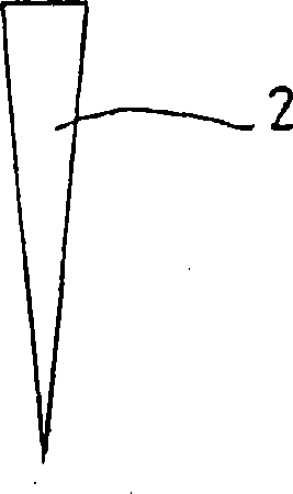
[0026] figure 1 A side view of a conventional machete 1 is shown, which consists of a blade and / or blade 2 , a knob 3 and a handle 4 . Knob 3 is here the connection piece of knife plate and / or blade 2 and handle 4, and has figure 2 The shape shown in the cross-sectional view. When using the machete 1 , it is possible for fingers to come into contact with the blade and / or the shank-side surface 5 of the blade 2 . However, this surface 5 is not adapted to the anatomy of the fingers, so handling the machete 1 is uncomfortable.

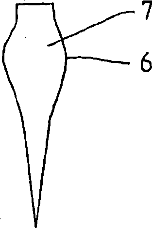
[0027] image 3 A knob 6 according to the invention is shown, which, in contrast to the cross-section of the blade and / or blade 2 , is designed wider than the blade and / or blade 2 at point 7 . This avoids uncomfortable pressure points on the resting finger when using the machete, since the finger rests on the wider point 7 .

[0028] Figure 4 A further advantageous embodiment of a machete 8 according to the invention is shown, which has a knob 6 a...


PUM


Abstract

The present invention relates to a cleaver (8) having a crush-forged crank (6). In order to provide a cleaver having an improved manageability and surface feel, thereby preventing any possible injuries during the use of the cleaver, the invention proposes that the crank (6) according to the invention extends from the handle (4) in the direction of the cutting edge (11) along the edge surface (5) on the handle side. And if a bolster front edge (17) resting on a side face of the blade (2) of the crank extends obliquely in such a manner that an upper end (19) of the edge (17) is closer to a front edge (20) of the blade (2) than a lower end (21) of the edge (17). The cleaver (8) is manufactured from a blank stamped in one piece.

Description

technical field [0001] The invention relates to a machete with an upset knob. Background technique [0002] Machetes with upset knobs are known, which comprise a blade and / or a blade, a knob and a handle, wherein the handle and blade and / or blade are interconnected via the knob . Also known are knives in which the blade, the knob and the shank (Erl) are produced from a blank by upsetting. [0003] FR 2 612 432 A1 discloses a method, for example, for producing a machete consisting of several elements, in which the shank is connected to the blade by means of an upset knob. On the other hand, GB 692 042 A discloses a method for producing knives in which a blank punched out of a hard and non-rusting material is processed into a knives with upset knives (handles). [0004] When using known machetes, there may be contact between the fingers holding the handle and the surface of the blade and / or the surface of the blade on the tang side. Uncomfortable pressure points can thus f...

Claims


Application Information

Patent Timeline
Patent Type & Authority Applications(China)
IPC IPC(8): B26B23/00B26B9/00B21K11/02B21D53/64
CPCB26B29/02B21K11/02B26B3/00
Inventor J·德勒泽
Owner ZWILLING J A HENCKELS
Why Eureka
Try Eureka