Discharge lamp operation device and illumination device
一种点亮装置、放电灯的技术,应用在照明装置、电光源、电气元件等方向,能够解决难以维持点亮的状态、反馈控制精度恶化、放电灯光输出降低等问题,达到抑制光输出的降低、提高补正动作、防止闪烁或中断的效果
- Summary
- Abstract
- Description
- Claims
- Application Information
AI Technical Summary
Problems solved by technology
Method used
Image
Examples
no. 1 Embodiment approach
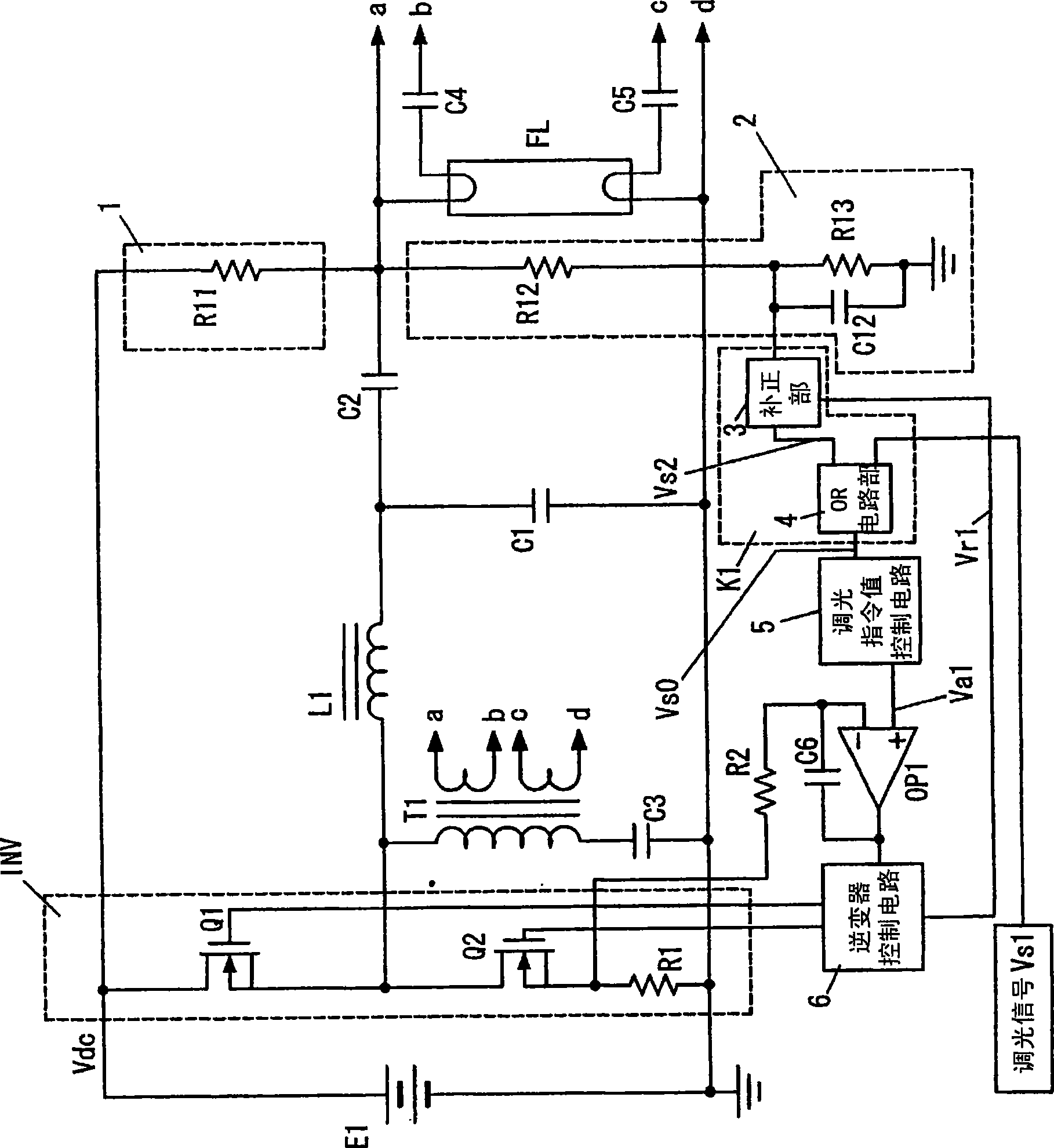
[0047] figure 1 is a circuit diagram showing the configuration of the discharge lamp lighting device according to the first embodiment, and Figure 11 In the conventional structure shown, the discharge lamp lighting device has: a DC superimposition circuit 1 and a dimming signal correction circuit K1. The connection point between the fluorescent lamp FL and the capacitor C2 is connected, whereby the high-frequency AC voltage applied to the fluorescent lamp FL from the inverter circuit INV overlaps with a small DC voltage component; The dimming signal is corrected by the DC voltage component of the fluorescent lamp FL, and the discharge lamp lighting device outputs the output of the dimming signal correction circuit K1 to the dimming command value control circuit 5 . other structures with Figure 11 The existing structures shown are the same, and the same symbols are assigned to the same structures, and explanations are omitted.
[0048] The lighting and warm-up operations of...
no. 2 Embodiment approach
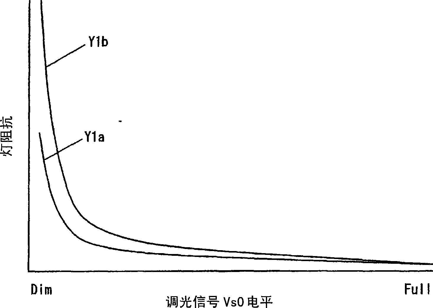
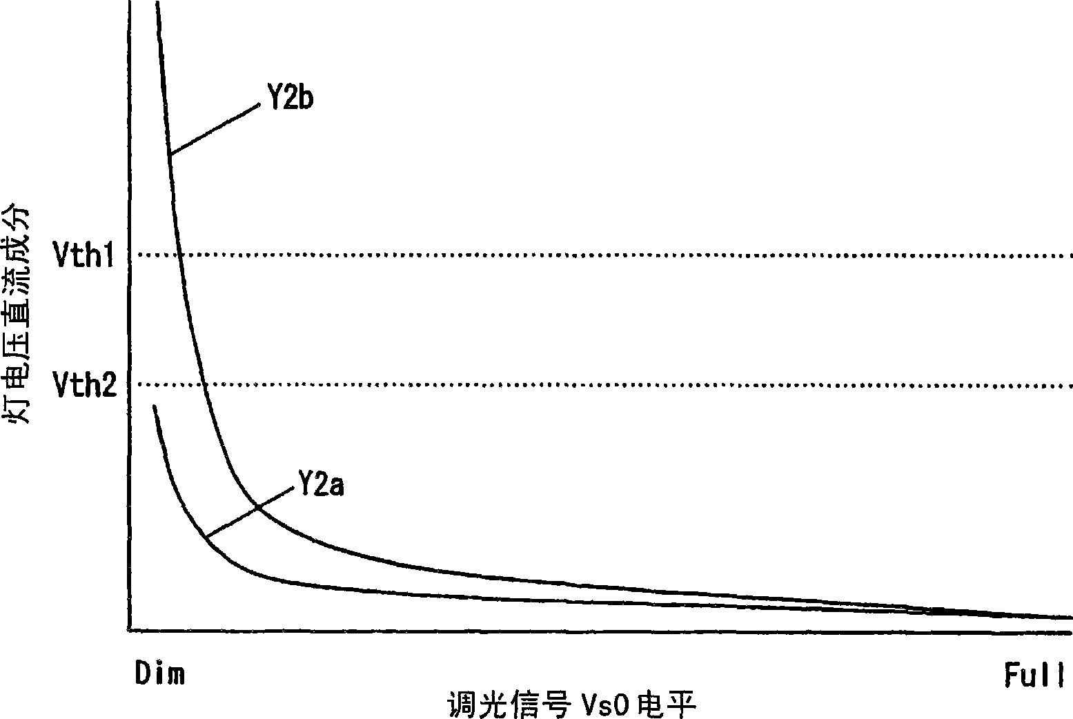
[0065] The discharge lamp lighting device of the second embodiment has a function of detecting the end-of-life state of the fluorescent lamp FL (discharge lamp) added to the structure of the discharge lamp lighting device of the first embodiment. The operation of the discharge lamp lighting device is as follows: Figure 4 (a), Figure 4 (b), Figure 4 (c) shown. In addition, similarly to the discharge lamp lighting device of the first embodiment, the figure 1 The circuit structure of the discharge lamp lighting device of 2nd Embodiment is shown in , the same code|symbol is attached|subjected to the same structure, and description is abbreviate|omitted.
[0066] Generally, at the end of the life of the discharge lamp, rectification of the discharge lamp occurs (asymmetry of the lamp current due to half-wave discharge), and the DC voltage component of the voltage across the discharge lamp increases. However, in the low-beam dimming region where the lamp current decreases, e...
no. 3 Embodiment approach
[0073] Figure 5 It is a circuit diagram showing the configuration of the discharge lamp lighting device according to the present embodiment. In the third embodiment, an AC voltage detection circuit 7 and a comparator circuit for detecting the AC voltage component at both ends of the fluorescent lamp FL are added to the configuration of the first embodiment. 8. The comparison circuit 8 compares the detection value of the AC voltage detection circuit 7 with the third threshold value Vth3, and outputs an oscillation stop signal for stopping the switching operation of the switching elements Q1 and Q2 to the inverter control circuit 6 based on the comparison result. Vr2. In addition, the same code|symbol is attached|subjected to the same structure as 1st Embodiment, and description is abbreviate|omitted.
[0074] The AC voltage detection circuit 7 is composed of the following components: a series circuit of resistors R14 and R15 connected between one end of the fluorescent lamp F...
PUM
 Abstract
Description
Claims
Application Information
 - R&D
- Intellectual Property
- Life Sciences
- Materials
- Tech Scout
- Unparalleled Data Quality
- Higher Quality Content
- 60% Fewer Hallucinations
Browse by: Latest US Patents, China's latest patents, Technical Efficacy Thesaurus, Application Domain, Technology Topic, Popular Technical Reports.
© 2025 PatSnap. All rights reserved.Legal|Privacy policy|Modern Slavery Act Transparency Statement|Sitemap|About US| Contact US: help@patsnap.com


