Buccal multi-bending spring space three-dimensional dynamometer

A three-dimensional dynamometer, buccal technology, applied in medical science, dentistry, etc., can solve problems such as poor retention of appliances

Inactive Publication Date: 2012-07-25
侯录 +1
View PDF8 Cites 0 Cited by
  • Summary
  • Abstract
  • Description
  • Claims
  • Application Information

AI Technical Summary

Problems solved by technology

[0002] At present, orthodontics at home and abroad, for early class III malocclusion During correction, movable appliances are often used for correction, and these appliances have the defect of poor retention

Method used


Image

  • Buccal multi-bending spring space three-dimensional dynamometer
  • Buccal multi-bending spring space three-dimensional dynamometer
  • Buccal multi-bending spring space three-dimensional dynamometer

Examples


specific Embodiment approach 2

[0034] Clinicians correct patient errors Deformity, before wearing the buccal multi-curved spring movable appliance in the mouth, the mandibular overshoot on both sides of the buccal multi-curved spring is simulated on the buccal multi-curved spring space three-dimensional dynamometer. point, in the process of opening and closing the mouth, its motion trajectory (three-dimensional space) is consistent with that of the maxillary The changing law of the point compressive stress value (from the maximum compressive stress to the minimum compressive stress or change to tensile stress) can comprehensively predict the force on the entire dentition of the upper and lower jaws, that is, simulate the mandibular transition. The point (both sides) is simplified as the multi-curved spring on the buccal side goes up and down The three-dimensional coordinate movement of a point in space.

[0035] The first type: lower jaw point (both sides) from the closed state to the maximum openi...

specific Embodiment approach 3

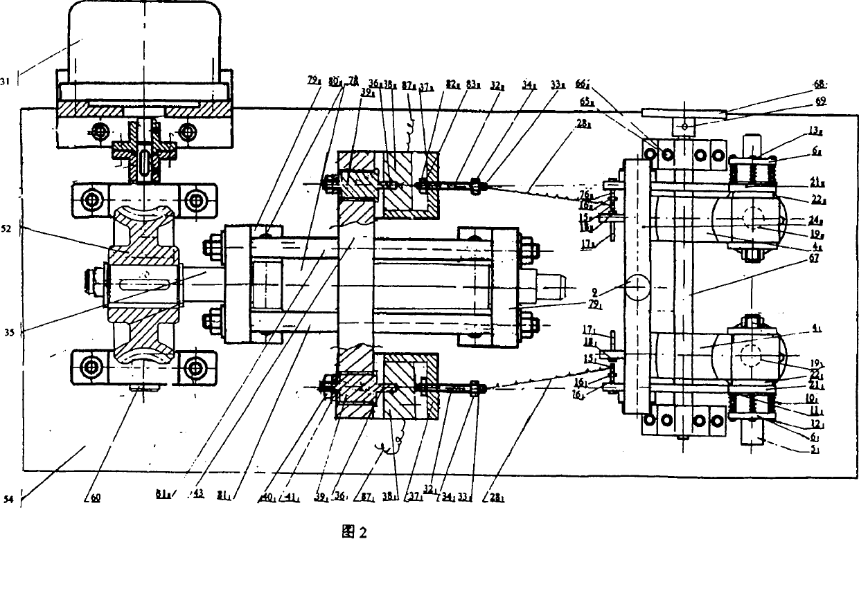
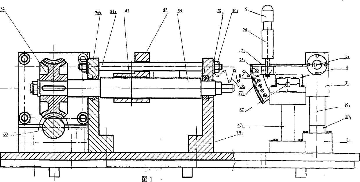
[0038] The motor 31 can be changed to a continuously variable speed motor, and then through the worm gear variable speed transmission, completes the uniform motion and completes the drive; the synchronous three-dimensional mobile handle 9 and the synchronous displacement plate 24 can also be changed to a continuously variable speed motor to drive and complete the displacement stress test. before (see attached figure 2 , 8 , 9, 10).

[0039] working principle:

[0040] The invented space three-dimensional dynamometer is based on the orthodontic error of clinical patients. During the correction process, the condyle is regarded as a simple rotational movement (hinge movement) without sliding. The resulting opening range (hinge opening) is 18-20mm between the incisal margins of the upper and lower incisors. The mandible moves in a three-dimensional space. point, chin point, and its landmark points are displaced relative to the coordinate system. Considering that the hinge c...


PUM


Abstract

The invention relates to a buccal multi-bending spring space three-dimensional dynamometer (in figure 2), which is applied to simulating a maxilla, a mandible and a temporom and ibular joint, and predicting the push and pull force values generated on crossover points of the maxilla and the mandible when a correction patient wears multi-bending springs 28I and 28II to perform mouth opening and closing motions. The dynamometer has accurate measurement and can instruct the clinical allopathic wearing according to the following steps: (1) putting two terminal filaments of the 28I and the 28II into a 15I, a 15II and upper jaws 33I and 33II fastening the terminal filaments, and moving a bracket 43 leftwards and rightwards so as to measure the pulling-pressing stress values and the displacements of the 28I and the 28II to a full denture; (2) elongating the 28I and the 28II, fastening the same into holes of the 15I, the 15II, the 33I and the 33II, moving a 32I and a 32II to adjust the stress values to approach to 0, driving a 35, the 32I and the 32II to move rightwards, and measuring the maximum pressing stress value of the full denture of the upper jaw and the lower jaw when the 28I and the 28II are pressed to a mouth-closing state; and (3) measuring the stress values and the displacements of the 28I and the 28II along the scales of 5 degrees, 10 degrees and 15 degrees of a 8I and a 8II by the 15I and the 15II; and if a 21I and a 21II move around a center leftwards and rightwards (the 15I and the 15II are 3 millimeters away from the central displacement), repeating the steps (1) and (2) to measure acting forces and displacement values.

Description

technical field [0001] The present invention involves wrong During the correction process, when the patient wears the buccal multi-curved spring movable appliance in the mouth, when the mandible moves to open and close the mouth, and the three-dimensional displacement changes in different time periods, at a certain moment, the more the multi-curved spring acts on the upper jaw. point, lower jaw Each point will be subjected to multi-bend spring tension and compression stress, its displacement in the oral cavity and the value of the force generated by the spring, the change law is unknown, and the stress value is also difficult to measure. The invented space three-dimensional dynamometer can solve this problem. point, lower jaw The movement trajectory of the point and the three-dimensional movement law of the space are simulated on a dynamometer to directly and accurately test the displacement of the curved spring mark point in space, the static, dynamic, and force value...

Claims


Application Information

Patent Timeline
Patent Type & Authority Patents(China)
IPC IPC(8): A61C19/04
Inventor 徐实谦侯录康毅志何志伟刘笑笑王阿娜
Owner 侯录
Why Eureka
Try Eureka