Method for assembling telescopic screw

An assembly method and sleeve technology, applied in the direction of screws, nuts, bolts, etc., can solve the problems of loose sleeve 15, lack of assembly method, inconvenience, etc.

Inactive Publication Date: 2009-08-26
FIVETECH TECH INC
View PDF0 Cites 1 Cited by
  • Summary
  • Abstract
  • Description
  • Claims
  • Application Information

AI Technical Summary

Problems solved by technology

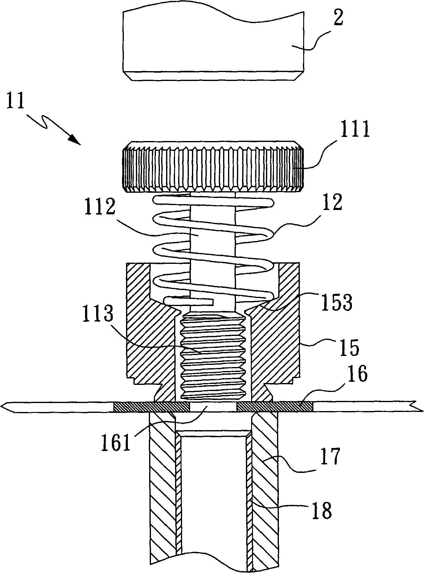
However, in the existing known sleeve screw assembly method, the threaded section 112 of the screw 11 penetrates the inner edge of the perforated hole 161 of the gasket material 16, which makes the inner edge of the annular gasket 14 cut out by the annular cutter 18 be worn by the threaded section 113. Enlarging the inner diameter indirectly weakens the supporting force of the inner edge of the ring washer 14 against the upper end of the threaded section 113, and finally when the sleeve 15 is movably assembled on the screw 11, the sleeve 15 is easily loosened from the threaded section 113 of the screw 11.
In addition, the conventional sleeve screw assembly method is to compensate for the enlarged inner diameter of the inner edge of the ring washer 14 due to wear, so the size of the ring washer 14 needs to be enlarged in advance, which makes the overall size of the sleeve screw 1 also need to be enlarged and cannot be reduced. change
Furthermore, the existing known socket screw assembly method requires the use of assembly tools with complex structures, such as the pressing tool 2, the annular seat body 17 and the annular cutter 18, etc., thereby increasing the manufacturing cost
[0004] This shows that above-mentioned existing sleeve screw assembly method obviously still has inconvenience and defect in method and use, and needs to be further improved urgently
In order to solve the above-mentioned problems, the relevant manufacturers have tried their best to find a solution, but no suitable design has been developed for a long time, and the general assembly method has no suitable method to solve the above-mentioned problems. This is obviously related. The problem that the industry is eager to solve

Method used


Image

  • Method for assembling telescopic screw
  • Method for assembling telescopic screw
  • Method for assembling telescopic screw

Examples


Embodiment Construction

[0034] In order to further explain the technical means and effects of the present invention to achieve the intended purpose of the invention, below in conjunction with the accompanying drawings and preferred embodiments, the specific implementation methods, methods, steps, Features and their functions are described in detail below.

[0035] The aforementioned and other technical contents, features and effects of the present invention will be clearly presented in the following detailed description of preferred embodiments with reference to the drawings. Through the description of the specific implementation mode, when the technical means and functions adopted by the present invention to achieve the predetermined purpose can be obtained a deeper and more specific understanding, but the accompanying drawings are only for reference and description, and are not used to explain the present invention be restricted.

[0036] see Figure 7 to Figure 12 as shown, Figure 7 It is a sc...


PUM


Abstract

The invention relates to a method for assembling a telescopic screw, which comprises the following steps: providing an annular base body, and placing an annular gasket at the upper end of the annular base body; providing a screw, a telescopic spring and a sleeve, wherein the screw is provided with a screw head which is provided with a screw rod section and a screw thread section by extending downwards sequentially, and the upper end of the sleeve is contracted with a through hole; making the screw thread section run through the telescopic spring and the through hole so that two ends of the telescopic spring are supported against the screw head and the sleeve respectively; and making diagonal threads of the screw thread section screwed in with gaps and run through the annular gasket so that the annular gasket is sleeved on the screw thread section and is limited between the downside of the through hole and the upper end of the screw thread section. The method has the effects of keeping a smaller inner diameter for the annular gasket so that the annular gasket is sleeved on the screw rod section of the screw more tightly, increasing the strength and the reliability for assembling the screw and the sleeve, reducing the volume of the annular gasket to further reduce the integral volume of the sleeve and the screw, and using a simpler assembling tool to reduce the manufacturing cost.

Description

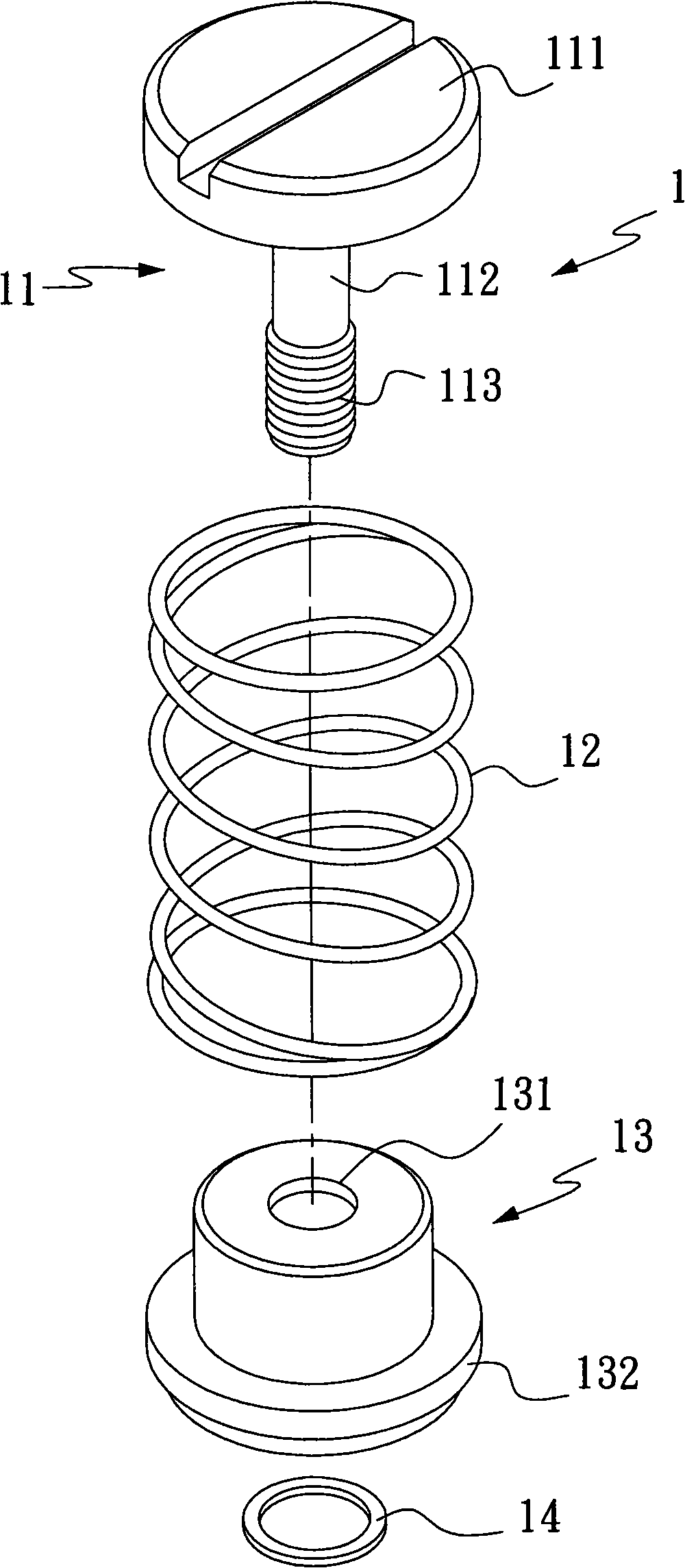
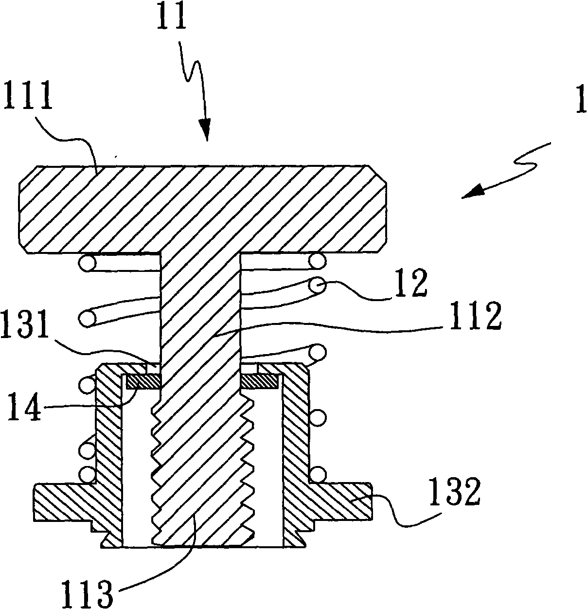
technical field [0001] The invention relates to an assembly method of a sleeve screw, in particular to a threaded section of a screw threaded through an annular washer, which increases the strength and reliability of the assembly of the screw and the sleeve, reduces the overall volume of the sleeve screw, and is easier to use The assembly tool can reduce the manufacturing cost of the sleeve screw assembly method. Background technique [0002] see figure 1 , figure 2 as shown, figure 1 It is an exploded three-dimensional schematic diagram of the structure of the existing known sleeve screw, figure 2 It is a schematic cross-sectional view of a known sleeve screw structure. The conventional sleeve screw 1 includes a screw 11 , a telescopic spring 12 , a sleeve 13 and an annular washer 14 . Wherein, the screw 11 has a screw head 111, and the screw head 111 extends downwards sequentially to provide a screw section 112 and a thread section 113; The outer top is against the...

Claims


Application Information

Patent Timeline
IPC IPC(8): F16B39/284
Inventor 王鼎瑞吴明德
Owner FIVETECH TECH INC
Why Eureka
Try Eureka