Series excited motor and speed regulation and control method thereof

A technology of series excitation motor and control method, applied in excitation or armature current control, electrical components, electromechanical devices, etc., can solve the problems of increasing harmonic current components, failing to pass certification tests, etc., to reduce harmonic current components , the effect of reducing the jump and reducing the harmonic current

Inactive Publication Date: 2012-06-27
金丰电子(苏州)有限公司
View PDF0 Cites 0 Cited by
  • Summary
  • Abstract
  • Description
  • Claims
  • Application Information

AI Technical Summary

Problems solved by technology

[0008] As mentioned earlier, due to the addition of a 25Hz beat due to the different processing methods of odd and even waves, it will cause an increase in the newly defined harmonic current component, especially the 4th harmonic that would not exceed the range originally, under the new definition would exceed the requirements and fail the certification test
[0009] Due to the limitations of the above-mentioned new definition of harmonic current, it is difficult to use the existing technology to suppress the harmonic component by controlling the conduction angle of adjacent wave cycles to pass the certification. The series excitation motor itself must be improved, and then Cooperate with the new speed control method to achieve real low harmonic speed control for series motors

Method used


Image

  • Series excited motor and speed regulation and control method thereof
  • Series excited motor and speed regulation and control method thereof
  • Series excited motor and speed regulation and control method thereof

Examples


Embodiment 1

[0024] Embodiment one: see attached figure 1 As shown in Figure 7,

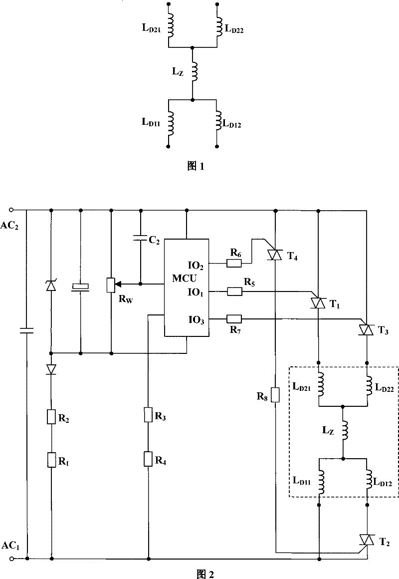
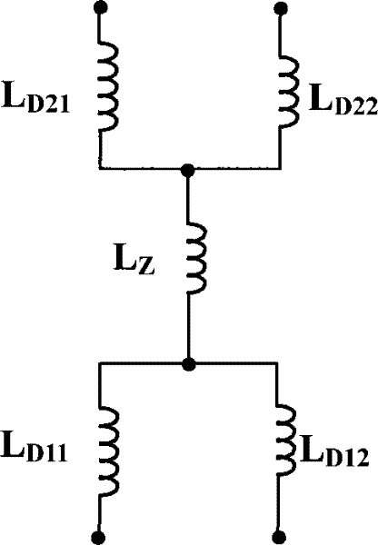
[0025] See attached figure 1 As shown, a series motor includes a rotor and a stator, and the rotor is provided with an armature winding L Z , the two poles of the stator are provided with field windings respectively, and a series circuit is formed between the field winding and the armature winding through brushes, wherein the field winding of one pole is formed by the low section winding L D11 and high section winding L D12 Composed of double winding structure, the low section winding L D11 and high section winding L D12 One end of the pole is connected to the brush, and the other end constitutes an independent outlet. The direction of the magnetic field generated by the low-section winding and the high-section winding is the same after the power is applied; the excitation winding of the other pole is formed by the low-section winding L D21 and high section winding L D22 Composed of double winding struc...


PUM


Abstract

The invention discloses a series excited motor. The motor comprises a rotor and a stator; the rotor is provided with an armature winding; two electrodes of the stator are provided with excitation windings respectively; and a series circuit is formed between the excitation windings and the armature winding by an electric brush. The series excited motor is characterized in that each excitation winding has a double-winding structure consisting of a low section winding and a high section winding; one end of the low section winding and one end of the high section winding are connected in parallel with the electric brush; the other end of the low section winding and the other end of the high section winding form independent wire outlet terminals respectively; and the direction of an electric field after each winding is electrified is consistent. According to the parameters of each winding, a power transformation point is set; under the power transformation point, bidirectional controlled silicons of two high section windings are cut off; conduction angles of bidirectional controlled silicons of the low section windings are adjusted; above the power transformation point, the bidirectional controlled silicons of the low section windings are fully conducted; and the conduction angles of one or two bidirectional controlled silicons of the high section windings are adjusted for realizingspeed regulation. The series excited motor can greatly reduce harmonic current in use and can adapt the change of a testing mode of the harmonic current.

Description

technical field [0001] The invention relates to a motor, in particular to a series-excited motor and a method for controlling the speed of the series-excited motor. Background technique [0002] The series motor is a motor commonly used in electrical products such as vacuum cleaners. Its structure includes a rotor and a stator. The rotor is provided with armature windings. The two poles of the stator are provided with field windings. The field windings of the two poles and the armature windings are connected by brushes. It forms a series circuit with the commutator; after electrification, the field windings of the two poles of the stator generate magnetic flux, and the current-carrying armature windings on the rotor interact with it to generate electromagnetic torque, thereby causing the rotor of the motor to rotate. The series-excited motor with this structure does not need a starting saturated capacitor, and has a simple structure and a fast speed, and has been widely used...

Claims


Application Information

Patent Timeline
Patent Type & Authority Patents(China)
IPC IPC(8): H02K23/26H02K3/28H02P7/28
Inventor 谢明毅
Owner 金丰电子(苏州)有限公司
Why Eureka
Try Eureka