
Re-entrant resonant cavities, filters including such cavities and method of manufacture

一种谐振腔、滤波器的技术,应用在凹腔谐振腔领域,能够解决实现谐振腔精确放置有害等问题,达到便宜制造方法、重量轻、良好频率控制的效果

Inactive Publication Date: 2009-08-26
LUCENT TECH INC
View PDF4 Cites 7 Cited by
  • Summary
  • Abstract
  • Description
  • Claims
  • Application Information

AI Technical Summary

Problems solved by technology

However, the unpredictable flow of solder during the process can be detrimental to achieving precise cavity placement

Method used


Image

  • Re-entrant resonant cavities, filters including such cavities and method of manufacture
  • Re-entrant resonant cavities, filters including such cavities and method of manufacture
  • Re-entrant resonant cavities, filters including such cavities and method of manufacture

Examples


Embodiment Construction

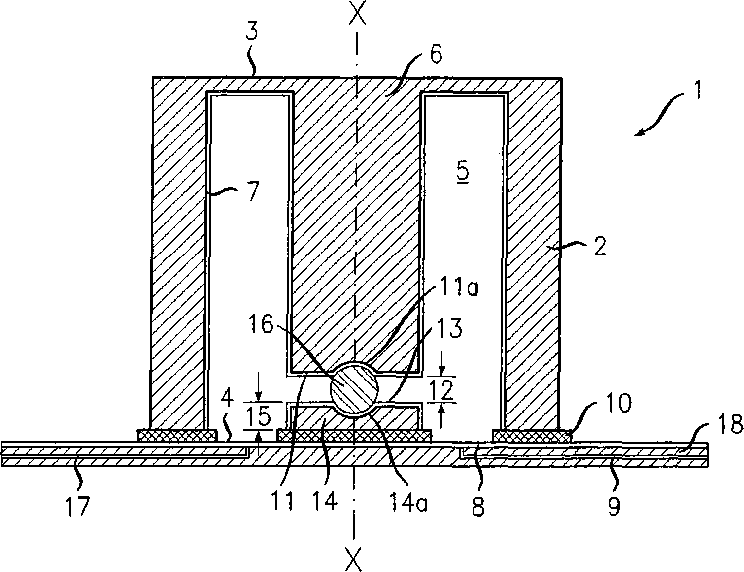
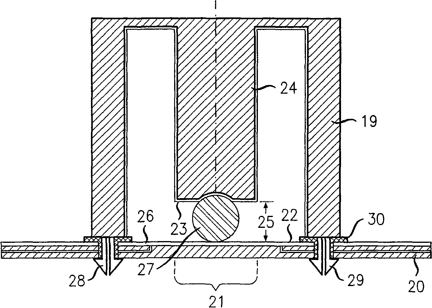
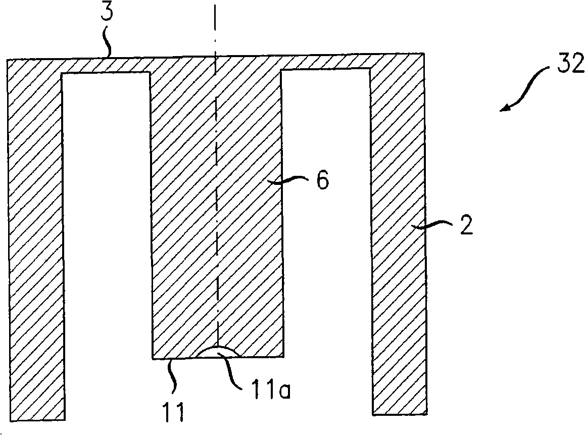
[0031] refer to figure 1 , a concave cavity microwave resonator 1 comprises a cylindrical wall 2 having first and second end walls 3 and 4 at each end to define a generally cylindrical shape therebetween. The volume of 5. Extending from the first end wall 3 into the volume 5 is a stud 6 positioned along the longitudinal axis X-X of the cylindrical wall 2 . The cylindrical wall 2 , the first end wall 3 and the stub 6 are integrally formed as a single molded plastic part, the inner surface of which is plated with a silver layer 7 . The thickness of the first end wall 3 is relatively thinner than that of the cylindrical wall 2 . The second end wall 4 is defined by a metallization 8 carried by a printed circuit board substrate 9 . The cylindrical wall 2 is bonded to the metallization 8 by the solder 10 laid down during the surface mount soldering process during the manufacturing process of the device.

[0032]The end face 11 of the stub 6 defines a gap 12 between said end face...


PUM


Abstract

A re-entrant microwave resonant cavity comprises a stub 6 . A cylindrical wall 2 , first end wall 3 and the stub 6 are integrally formed. A second end wall 4 is defined by a metallization layer 8 deposited on a printed circuit board substrate 9 . The parts are joined using surface mount soldering processes. The end 11 of the stub 6 defines a gap 12 . A rostrum 14 faces the end of the stub 6 . The rostrum 14 is manufactured separately and then fixed to the substrate 9 . A dielectric sphere 16 is located between the end 11 of the probe 6 and the rostrum 14 . The dielectric sphere 16 maintains the gap size during use and aids in correct positioning of the parts during manufacture.

Description

technical field [0001] The present invention relates to re-entrant resonator filters including re-entrant resonators and methods of manufacturing such re-entrant resonators. The present invention relates more particularly, but not exclusively, to cavity resonators suitable for fabrication using surface mount techniques. Background technique [0002] A resonant cavity is a device having an enclosed volume bounded by conductive surfaces within which an oscillating electromagnetic field is subjected. Resonant cavities can be used, for example, in filters, and have excellent power handling capabilities and low energy consumption. Several resonators can be coupled together for complex frequency selective performance. [0003] Since the geometry of the cavity determines its resonance frequency, high mechanical precision is required and in addition, or alternatively, post-production tuning is applied. For example, a tuning mechanism may be provided, such as a tuning screw that p...

Claims


Application Information

Patent Timeline
Patent Type & Authority Applications(China)
IPC IPC(8): H01P1/205H01P7/04
CPCH01P1/2053H01P7/04H01P1/205
Inventor 简·黑塞尔巴斯
Owner LUCENT TECH INC
Learn More