Regulating device of pulling rod

A technology for adjusting devices and stretching rods, which can be applied to other household appliances, household appliances, applications, etc., can solve problems such as troublesome operation and affecting the hygiene of bottles, and achieve the effects of convenient operation, cleanliness and sanitation, and concentricity

Inactive Publication Date: 2013-07-10
柯福友
View PDF1 Cites 0 Cited by
  • Summary
  • Abstract
  • Description
  • Claims
  • Application Information

AI Technical Summary

Problems solved by technology

The stretching cylinder of the plastic hollow container stretch blowing machine is generally placed vertically. There is a stretching rod in the stretching cylinder, which is connected to the stretching piston. There is a sealing cylinder on the stretching cylinder. In order to make the stretching mechanism suitable for different The height of the bottle is usually added to the stretching mechanism. The adjusting device disclosed in the patent No. ZL 200620108307.4 is to install the adjusting piece on the upper cylinder head of the stretching cylinder. The adjusting piece is set outside the stretching rod. The disadvantage is: since the stretching rod is located in the stretching cylinder, it is necessary to disassemble the stretching cylinder during adjustment, then insert or take out the adjustment parts of the corresponding height, and finally reinstall the stretching cylinder, the operation is quite troublesome
In addition, the sealing piston in the sealing cylinder described in this patent is connected to the sealing piece, and a through hole is formed in the sealing piston and the sealing piece for the passage of the stretching rod. When the sealing cylinder is working, the upper part of the stretching rod is exposed in the sealing cylinder. If it is stained with oil, since the upper part of the stretch rod needs to extend into the preform, it will affect the sanitation of the bottle, especially not suitable for products that require high hygienic conditions.

Method used


Image

  • Regulating device of pulling rod
  • Regulating device of pulling rod

Examples


Embodiment Construction

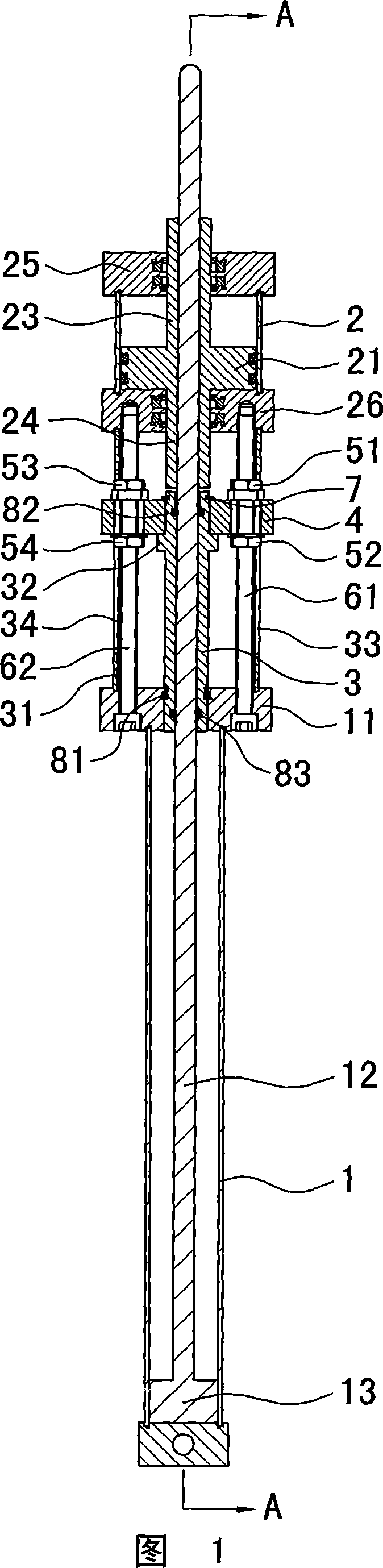
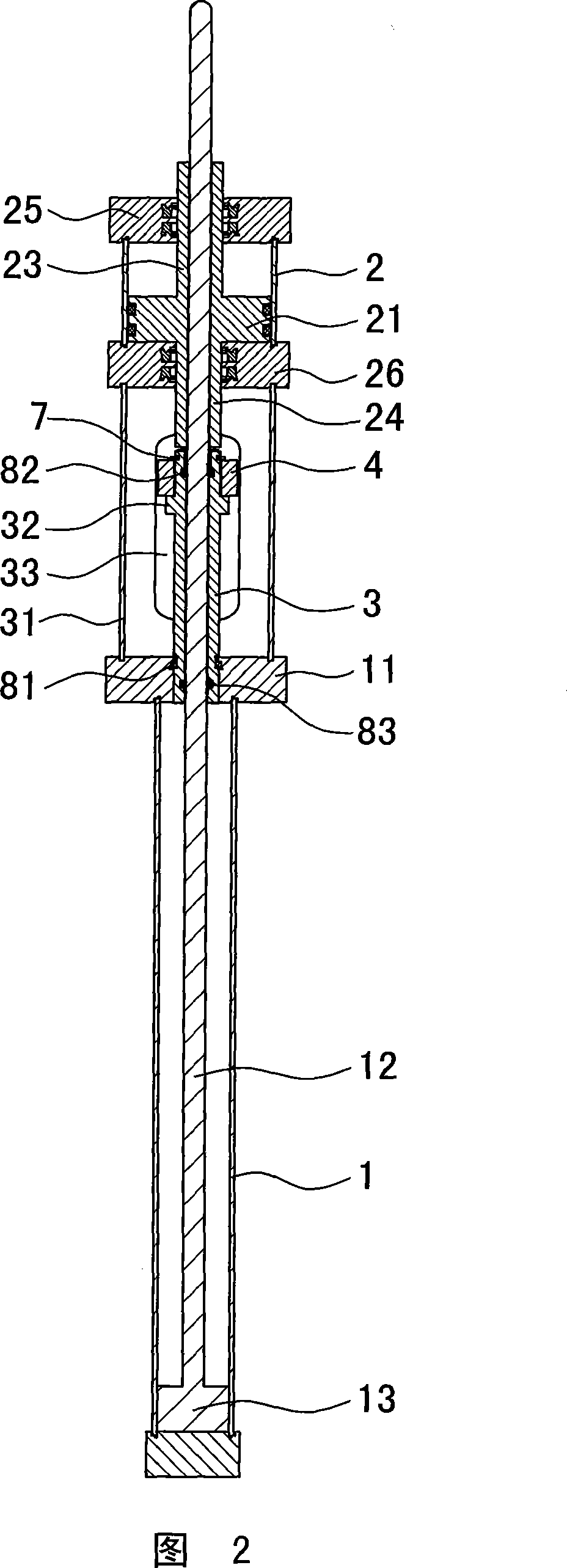
[0009] The invention discloses a stretching rod adjustment device, as shown in Figure 1 and Figure 2, there is a stretching cylinder 1 arranged vertically, a stretching rod 12 is arranged in the stretching cylinder, and the stretching rod is connected with a stretching piston 13 , a sealing cylinder 2 is arranged on the stretching cylinder, and a sealing piston 21 is arranged in the sealing cylinder, which is characterized in that a limit rod 3 is installed between the upper cylinder cover 11 and the stretch rod 12 for stretching, and the adjusting seat 4 is fixed on the limit rod, The two sides of the adjustment seat are respectively connected with the adjustment screw rods 61, 62 through the upper and lower adjustment nuts 51, 52, 53, 54. The adjustment screw rods are installed between the stretching upper cylinder head 11 and the sealing lower cylinder head 26. Bit cylinder liner 31. Compared with the prior art, the adjusting device is not installed in the stretching cylind...


PUM


Abstract

A regulating device of a pulling rod is provided with a vertically arranged pulling cylinder which is internally provided with a pulling rod connected with a pulling piston, the pulling cylinder is provided with a sealed cylinder which is internally provided with a sealed piston, and the regulating device is characterized in that a limiting rod is arranged between an upper pulling cylinder cover and the pulling rod, an adjusting seat is fixed on the limiting rod, the two sides of the adjusting seat are respectively connected with an adjusting screw rod by an upper adjusting nut and a lower adjusting nut, the adjusting screw rod is arranged between the upper pulling cylinder cover and a lower sealed cylinder cover, and the adjusting screw rod is externally provided with a limiting cylindersleeve. As the regulating device is arranged between the pulling cylinder and the sealed cylinder instead of being arranged inside the pulling cylinder, the pulling cylinder need not to be dismantledduring regulation, thus having convenient and quick operation; and the sealed cylinder and the pulling cylinder are connected with each other by the limiting cylinder sleeve, thus guaranteeing the concentricity of the sealed cylinder and the pulling cylinder well.

Description

technical field [0001] The invention relates to a stretching cylinder of a plastic hollow container stretch blowing machine, in particular to an adjusting device for a stretching rod in the stretching cylinder, belonging to the field of mechanical manufacturing. Background technique [0002] PET plastic bottles are widely used in filling various beverages, such as mineral water, juice drinks, tea drinks and dairy drinks, as well as medicine, cosmetics and other industries, which determines the broad market prospects of PET blow molding machines. PET plastic bottles are firstly injected with plastic raw materials into bottle tubes by injection molding machine, and then the plastic bottle tubes are heated, then stretched and blown by blow molding machine, and finally taken out. The stretching cylinder of the plastic hollow container stretch blowing machine is generally placed vertically. There is a stretching rod in the stretching cylinder, which is connected to the stretching...

Claims


Application Information

Patent Timeline
Patent Type & Authority Patents(China)
IPC IPC(8): B29C49/42B29C49/08B29L22/00
Inventor 柯福友
Owner 柯福友
Why Eureka
Try Eureka