Variable geometry turbine and turbocharger

A turbine and turbine rotor technology, applied in mechanical equipment, gas turbine devices, machines/engines, etc., can solve problems such as turbine capacity decline and achieve the effect of preventing capacity decline

Active Publication Date: 2009-09-02
MITSUBISHI HEAVY IND ENGINE & TURBOCHARGER LTD
View PDF7 Cites 15 Cited by
  • Summary
  • Abstract
  • Description
  • Claims
  • Application Information

AI Technical Summary

Problems solved by technology

Because of these Figure 14 and Figure 15 Fluctuations in the flow...

Method used


Image

  • Variable geometry turbine and turbocharger
  • Variable geometry turbine and turbocharger
  • Variable geometry turbine and turbocharger

Examples


no. 1 approach

[0053] Next, a first embodiment of a turbine and a turbocharger including the turbine according to the present invention will be described with reference to the drawings.

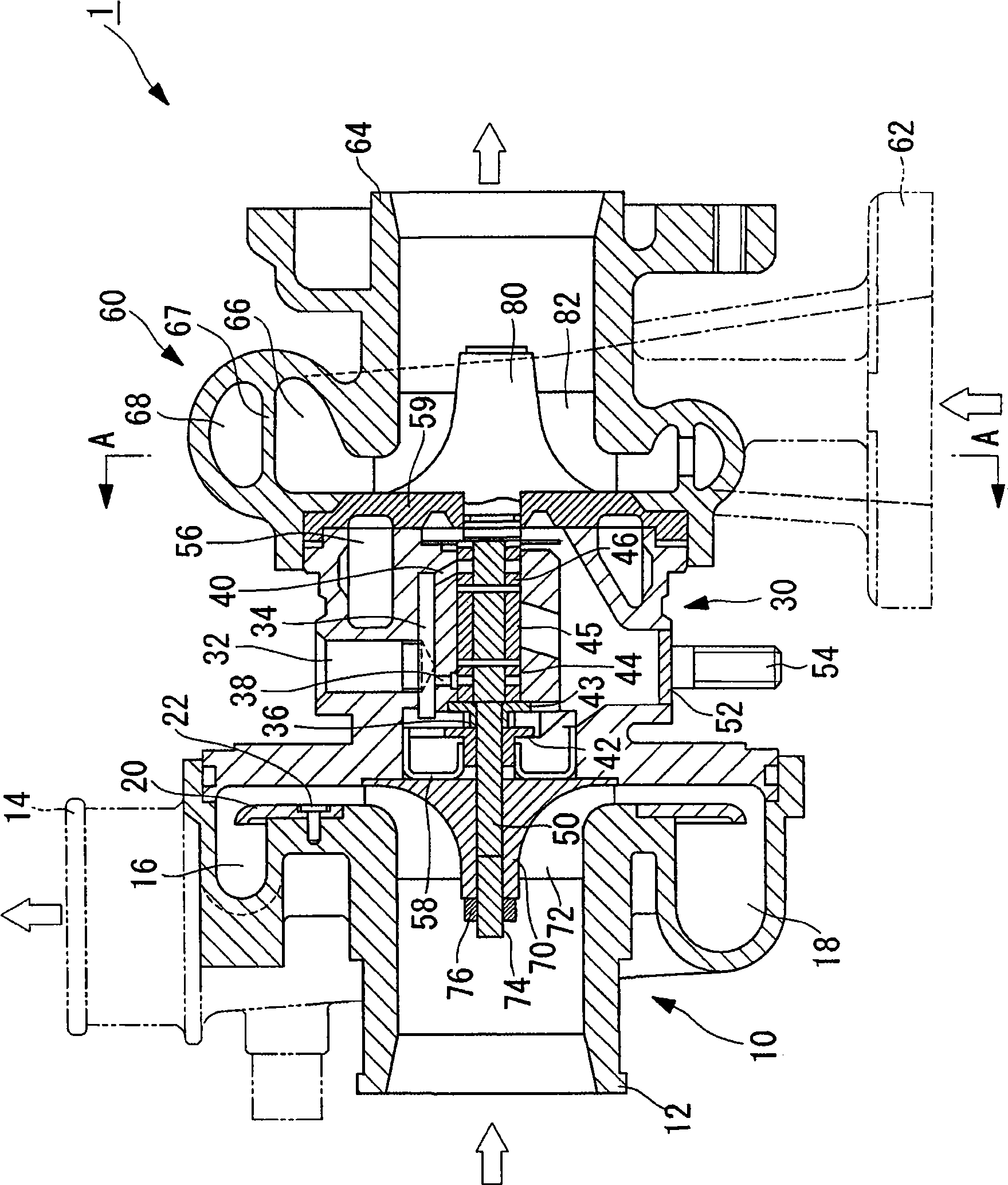
[0054] figure 1 A longitudinal section of the variable capacity turbocharger 1 according to the present embodiment is shown.

[0055] like figure 1 As shown, a compressor housing 10 is provided with a compressor inlet 12 , a compressor outlet 14 , and annular scrolls (scroll) 16 , 18 . The scrolls 16 and 18 extend from a position adjacent to the compressor discharge port 14 toward the outer circumference of the compressor housing 10 and communicate with the compressor discharge port 14 . Furthermore, the cross-sectional area is gradually enlarged as it approaches the compressor discharge port 14 . The supercharger 20 partitions the scroll tubes 16 and 18 and is mounted on the compressor housing 10 through bolts 22 .

[0056] A lubricating oil inlet 32 ​​is formed on the outer periphery of the bearing ...

no. 2 approach

[0069] Next, refer to Figure 8 and Figure 9 , the second embodiment of the present invention will be described.

[0070] The difference between the turbine of the present embodiment and the turbocharger equipped with the turbine and the first embodiment is that the flow path area A of the outer scroll portion 68 divided by the flow path area A of the outer scroll portion 68 is changed according to a predetermined rule. The value A / R of the distance R from the center to the center of rotation of the turbine rotor 80 . Hereinafter, the description of the same points of the turbine of the present embodiment and the turbocharger including the same as those of the first embodiment will be omitted, and the differences will be mainly described.

[0071] Figure 8 The relationship between A / R and the swirl angle is shown when the flow path area of ​​the outer scroll portion 68 is A and the distance from the center of the flow path of the outer scroll portion 68 to the rotation ce...


PUM


Abstract

A turbine (5) is provided which can reduce variations in mass flow at throats even when the flow rate of fluid is low or high, to prevent a decrease in performance. A turbine (5) includes a turbine rotor (80) which has turbine blades (82); a turbine housing (60) which accommodates the turbine rotor (80) and whose cross-sectional area of a scroll portion (100) formed between the turbine housing (60) and the turbine rotor (80) gradually decreases; a plurality of fixed vanes (102) which are fixed along a curved line dividing the scroll portion (100) into an inner scroll part (66) and an outer scroll part (68); throats (101) which are formed between the adjacent fixed vanes (102) and communicate between the inner scroll part (66) and the outer scroll part (68); and a switch valve (90) which switches a flow path in the turbine housing (60) either to the inner scroll part (66) or to both the inner scroll part (66) and the outer scroll part (68), wherein flow path areas of the throats (101) are reduced in a downstream direction of the scroll portion (100).

Description

technical field [0001] The present invention relates to a turbine and a turbocharger provided with the turbine, and the capacity of the turbine is variable. Background technique [0002] Conventionally, as a turbine included in a variable-capacity turbocharger, for example, a technique disclosed in JP-A-10-8977 is known. This turbine has a communication portion (hereinafter referred to as "throat") that divides the scroll portion into an inner scroll portion and an outer scroll portion in the radial direction, and is equipped with communication between these scroll portions; a switching valve , which switches whether the fluid flows into the inner peripheral scroll or either of the two scrolls. The flow path is switched by the switching valve according to the flow rate of the fluid. [0003] According to the above technique, when the flow rate of the fluid is small, the switching valve is operated to allow the fluid to flow only into the inner scroll portion, and torque is...

Claims


Application Information

Patent Timeline
IPC IPC(8): F02B37/22F02C6/12
CPCF02B37/025F01D17/145F02B37/225F02C6/12F05D2270/702F05D2220/40F05B2220/40Y02T10/144F01D9/026F02B37/22Y02T10/12F01D17/16
Inventor 松尾淳横山隆雄惠比寿干
Owner MITSUBISHI HEAVY IND ENGINE & TURBOCHARGER LTD
Why Eureka
Try Eureka