
Baffle device used in cooling zone of Muffle furnace

A technology of baffle device and cooling zone, which is applied in the mechanical field and can solve the problems of low temperature in the lower part of the cooling zone of the muffle furnace and high temperature in the upper part of the cooling zone of the muffle furnace.

Active Publication Date: 2009-09-02
IRICO
View PDF0 Cites 0 Cited by
  • Summary
  • Abstract
  • Description
  • Claims
  • Application Information

AI Technical Summary

Problems solved by technology

[0005] It can be seen from the above functional division that the upper part of the cooling area of ​​the muffle furnace needs to be heated to a certain temperature to ensure the safe use of the overflow tank, while the lower part needs to rapidly cool the glass plate, and in the existing technology, it cannot be done immediately. The temperature in the upper part of the muffle furnace cooling area is high, and the temperature in the lower part of the muffle furnace cooling area is low. Therefore, a baffle device is designed between the upper and lower parts of this area.

Method used


Image

  • Baffle device used in cooling zone of Muffle furnace
  • Baffle device used in cooling zone of Muffle furnace

Examples


Embodiment Construction

[0010] The present invention is described in further detail below in conjunction with accompanying drawing:

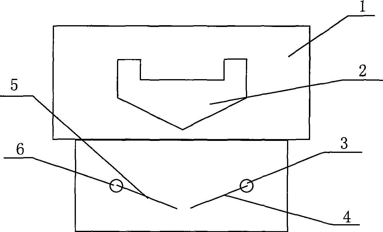
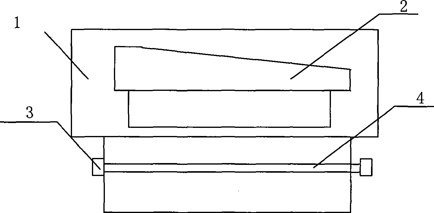
[0011] see figure 1 , 2 , a muffle furnace cooling zone baffle device, including muffle furnace 1, overflow tank 2, right-handed rod 3, right baffle plate 4, left baffle plate 5 and left-handed rod 6, set right under the overflow tank 2 Rotary bar 3 and left-handed bar 6, the side of right baffle 4 is fixed on the right-handed bar 3, the side of left baffle 5 is fixed on the left-handed bar 6, and right baffle 4 rotates around the inside of right-handed bar 3, Left baffle plate 5 rotates around the inboard of left-handed bar 6, and right-handed bar 3 controls the rotation of right baffle plate 4, and left-handed bar 6 controls the rotation of left baffle plate 5.

[0012] The right baffle plate 4 and the left baffle plate 5 are all placed horizontally, and the right baffle plate 4 and the left baffle plate 5 are butted into a plane. When it is necessary to adjust the...


PUM


Abstract

The invention discloses a baffle device used in a cooling zone of a Muffle furnace. The baffle device comprises a Muffle furnace, an overflow groove, a right rotating rod, a right baffle, a left baffle and a left rotating rod, wherein the right rotating rod and the left rotating rod are arranged below the overflow groove; the side edges of the right baffle are fixed on the right rotating rod, while the side edges of the left baffle are fixed on the left rotating rod; and the right rotating rod controls the right baffle to rotate around the inner side of the right rotating rod, while the left rotating rod controls the left baffle to rotate around the inner side of the left rotating rod. The baffle device has the advantages that the device reduces the influences on the upper part of the cooling zone of the Muffle furnace and the tip of the overflow groove caused by cooling airflow at the lower part of the cooling zone; the upper part and the lower part of the Muffle furnace are effectively divided in space to obtain greater adjustment margin in the function for each part; and the baffles can effectively assist the lower part of the Muffle furnace in cooling a glass sheet.

Description

Technical field: [0001] The invention belongs to the field of machinery and relates to a muffle furnace cooling zone baffle. Background technique: [0002] Below the overflow tank in the muffle furnace is the area where the glass needs to be shaped quickly. In this area, the glass plate achieves the purpose of shaping by various means. [0003] The heater in the cooling area of ​​the muffle furnace is divided into upper and lower parts. The heating surfaces of the upper and lower heaters cover the entire glass plate and are symmetrically distributed with the glass plate. There is a layer of specially processed uniform temperature plate in front of the upper heater. The material is mainly composed of silicon carbide. The heat of the heater can be evenly heated to the surface of the glass plate through the silicon carbide plate, and there is no damage to the tip of the overflow tank. Heated atmosphere with uneven hot and cold. When the overflow tank in the muffle furnace is ...

Claims


Application Information

Patent Timeline
IPC IPC(8): F27B5/06
Inventor 李文军
Owner IRICO
Features
  • Generate Ideas
  • Intellectual Property
  • Life Sciences
  • Materials
  • Tech Scout
  • Unparalleled Data Quality
  • Higher Quality Content
  • 60% Fewer Hallucinations
Learn More