Automatic monitor for angle of base station antenna and automatic monitoring method

A base station antenna and automatic monitoring technology, applied in the wireless field, can solve problems such as unstable measurement results, communication quality degradation, and inability to accurately meet design requirements, so as to solve manual measurement errors or instability, reduce maintenance and optimization costs, The effect of saving manpower and material resources

Active Publication Date: 2009-09-02
CHINA MOBILE GROUP JIANGSU
View PDF0 Cites 50 Cited by
  • Summary
  • Abstract
  • Description
  • Claims
  • Application Information

AI Technical Summary

Problems solved by technology

[0007] 1. Due to the different experience and construction methods of construction personnel in actual engineering construction, manually measuring the azimuth and downtilt angle of mobile communication base station antennas requires engineering and technical personnel to use a compass to manually determine the azimuth, and also requires engineering and technical personnel to pass Visually inspect the low-accuracy scale markings represented on the antenna's mounting bracket, identifying slopes that can lead to differences in engineering personnel's skill or manual measurement methods, resulting in incorrect or unstable measurements
Unable to accurately meet the design requirements
[0008] 2. In order to obtain the angle information of the base station antenna, engineers and technicians must directly climb up the base station antenna installed on the multi-storey building or iron tower, and use a compass at the antenna position. Due to the magnetic interference near the iron tower, measuring near the iron tower will cause more big error
It is generally required to have a certain distance away from the iron tow

Method used


Image

  • Automatic monitor for angle of base station antenna and automatic monitoring method
  • Automatic monitor for angle of base station antenna and automatic monitoring method
  • Automatic monitor for angle of base station antenna and automatic monitoring method

Examples


Embodiment Construction

[0040] The present invention will be described in detail below in conjunction with the accompanying drawings and embodiments.

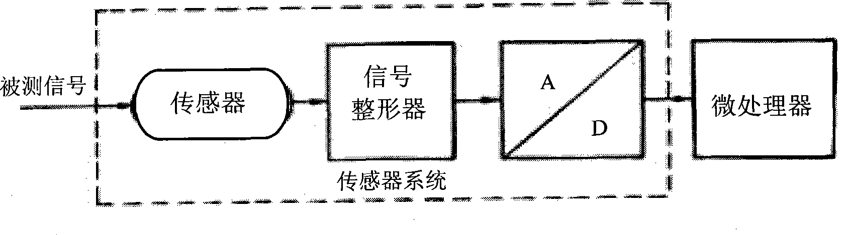
[0041] "A sensor is a pre-component in a measurement system that converts an input variable into a measurable signal." Such as figure 1 Shown is the block diagram of the sensor system.

[0042] 1. Technical solution for downtilt angle measurement

[0043] (1) Principle of acceleration sensor

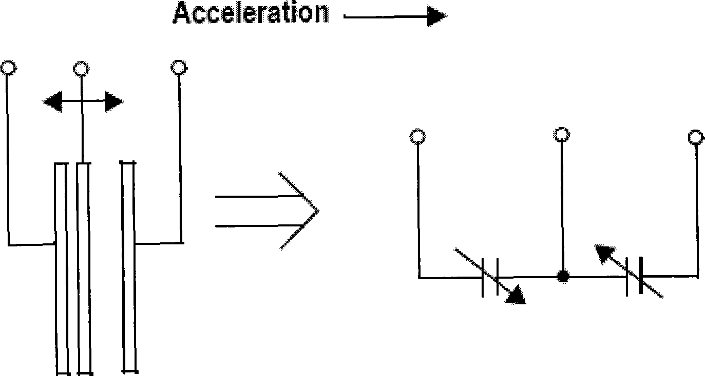
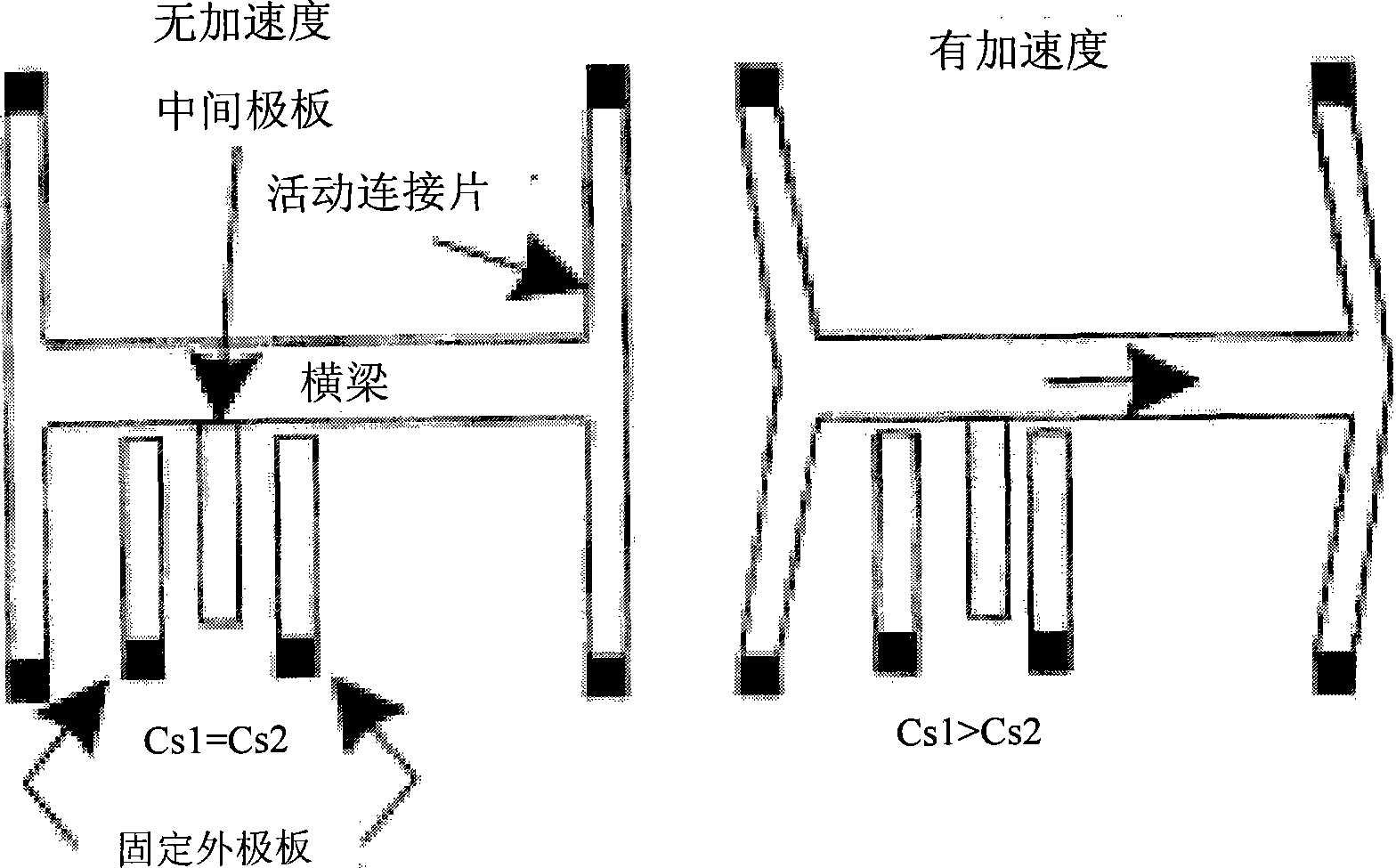
[0044] The most basic principle of the acceleration sensor is that a certain medium is deformed due to acceleration. By measuring its deformation and converting it into a voltage output with related circuits, the voltage is used to represent the magnitude of the acceleration.

[0045] The sensor mainly consists of a surface micromachined polysilicon body and a differential capacitor. The polysilicon structure is supported by polysilicon springs on top of the wafer and is connected to the moving center plate of the differential capacitor. Add two square wave...


PUM


Abstract

The invention discloses an automatic monitor for an angle of a base station antenna and an automatic monitoring method. The monitor and the method utilize an MEMS sensor to accurately measure a lower inclination angle of the base station antenna through the principle of a gravity accelerometer, utilize the principle of a reluctance sensitive device sensor to measure an azimuth angle of the base station antenna and calculate and correct the azimuth angle so as to eliminate the deviation caused by magnetic disturbance measured by the position of the antenna and ensure the measuring accuracy, and utilize GPRS transmission and IP transmission modes to automatically transmit the antenna angle data obtained by measuring to a network management center. The monitor and the method solve the inaccurate problems on installation and adjustment of the base station antenna in the prior modes, solve manual measurement error or instability, solve the measurement error influenced by the magnetic disturbance at the position of the antenna, solve the problem that the antenna angle change is not discovered in time, and solve the problem of time and labor wastes for acquiring the antenna angle information.

Description

technical field [0001] The present invention relates to the wireless field. Background technique [0002] Mobile communication base station antenna azimuth, downtilt, antenna height and performance parameters of the antenna itself determine the coverage of the base station, and as the main engineering parameters of the antenna (antenna azimuth, downtilt and antenna height) are wireless network planning The accuracy of important parameters, antenna azimuth and downtilt is an important factor affecting the call quality and perception of mobile users. How to quickly obtain the precise value of the antenna angle? It is particularly important for wireless network planning and optimization. [0003] At present, the azimuth and downtilt angle of the antenna of the mobile communication base station are obtained manually on site through visual measurement of instruments such as a compass (compass) and an inclinometer. The general methods are: [0004] To measure the azimuth angle...

Claims


Application Information

Patent Timeline
IPC IPC(8): G01C1/00H04B17/00
Inventor 王星昌吴泳健刁一新赵宏亮吴杰蔡伟明李楠
Owner CHINA MOBILE GROUP JIANGSU
Why Eureka
Try Eureka