Inductor and manufacturing method thereof

An inductor and electrical connection technology, applied in the direction of inductor/transformer/magnet manufacturing, transformer/inductor core, transformer/inductor coil/winding/connection, etc., can solve the problem of inductor and magnetic bead compounding

Active Publication Date: 2012-12-05
SHENZHEN ZHENHUA FU ELECTRONICS
View PDF0 Cites 0 Cited by
  • Summary
  • Abstract
  • Description
  • Claims
  • Application Information

AI Technical Summary

Problems solved by technology

At present, there is no composite technology of inductors and magnetic beads

Method used


Image

  • Inductor and manufacturing method thereof
  • Inductor and manufacturing method thereof

Examples


Embodiment Construction

[0024] In order to make the object, technical solution and advantages of the present invention clearer, the present invention will be further described in detail below in conjunction with the accompanying drawings and embodiments. It should be understood that the specific embodiments described here are only used to explain the present invention, not to limit the present invention.

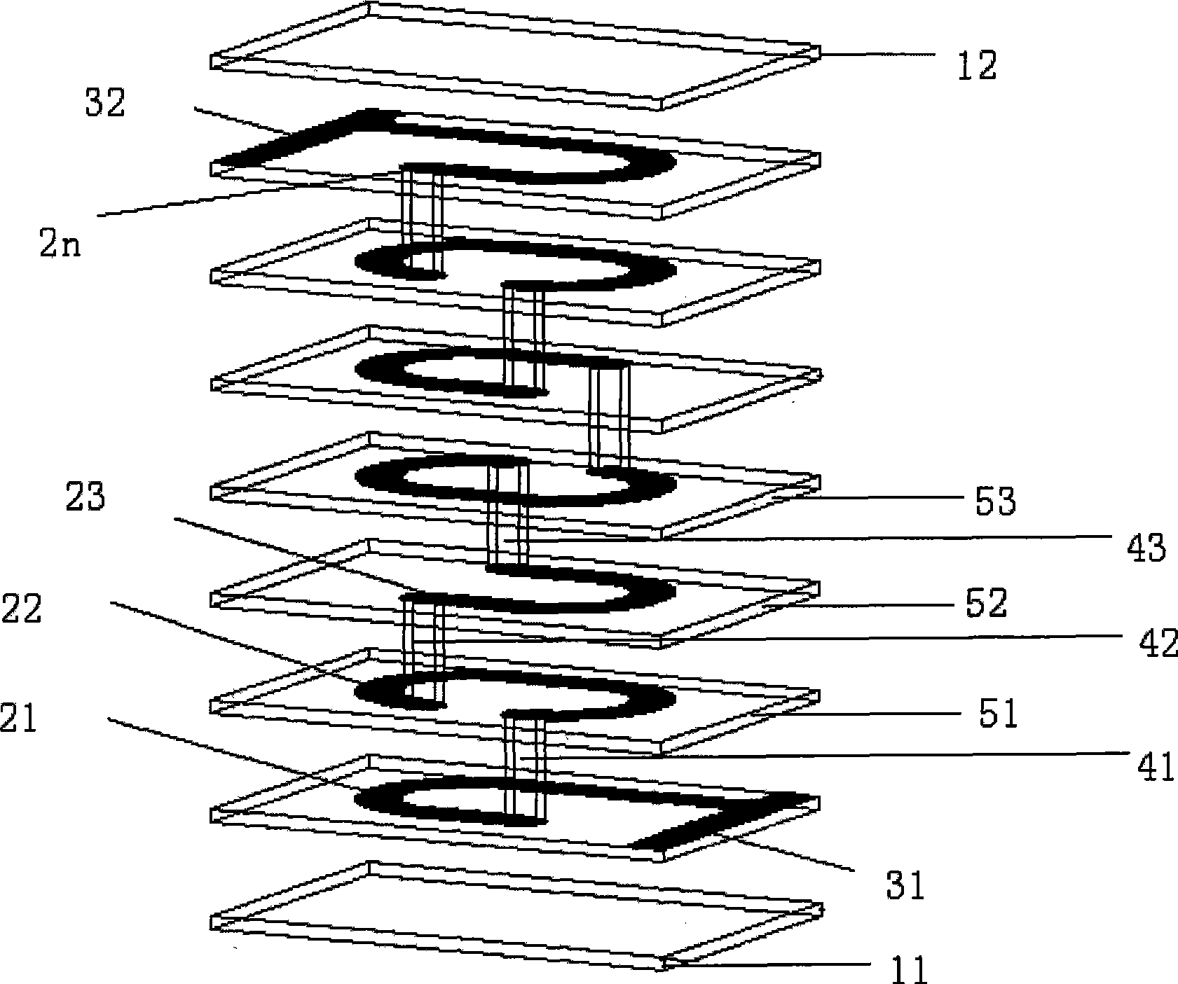
[0025] In the inductor provided in the embodiment of the present invention, the conductive coil adopts a quasi-elliptical spiral coil structure, so that the inductor has specific inductance characteristics and impedance characteristics at the same time.

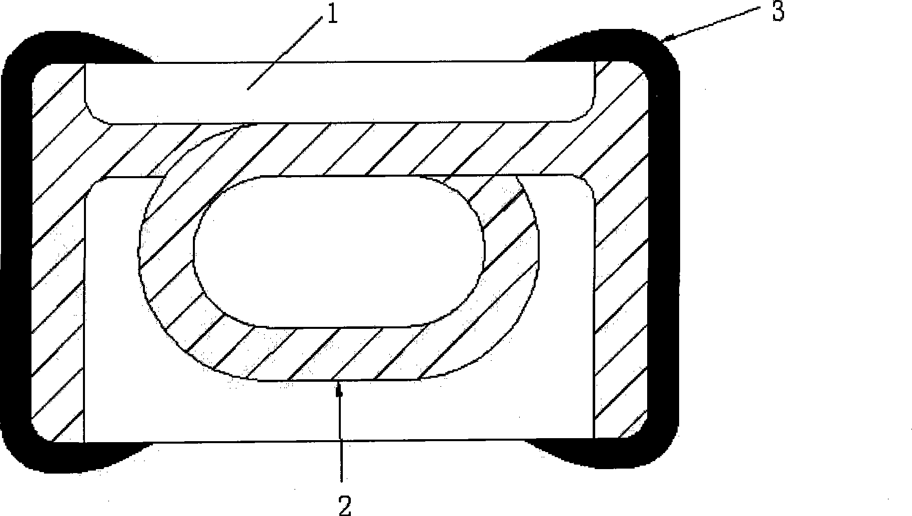
[0026] figure 1 The structure of the inductor provided by the embodiment of the present invention is shown. For the convenience of description, only the parts related to the present invention are shown, and the details are as follows.

[0027] The inductor includes: a ferrite substrate 1, a conductive coil 2 disposed in the ferrite substrate 1, a...


PUM

PropertyMeasurementUnit
sizeaaaaaaaaaa
inductanceaaaaaaaaaa

Abstract

The invention is suitable for the field of electronics, and provides an inductor and a manufacturing method thereof. The inductor comprises a ferrite substrate, a conductive coil arranged in the ferriThe invention is suitable for the field of electronics, and provides an inductor and a manufacturing method thereof. The inductor comprises a ferrite substrate, a conductive coil arranged in the ferrite substrate, and terminal electrodes which are positioned at two end parts of the ferrite substrate and used for electrically connecting with the conductive coil. The conductive coil comprises a plurte substrate, and terminal electrodes which are positioned at two end parts of the ferrite substrate and used for electrically connecting with the conductive coil. The conductive coil comprises a plurality of layers of electrode patterns which are connected layer upon layer spirally. The layers of the electrode patterns are electrically connected through electric connecting elements to form a spirality of layers of electrode patterns which are connected layer upon layer spirally. The layers of the electrode patterns are electrically connected through electric connecting elements to form a spiral ellipse-like shape. In the inductor provided by the invention, the conductive coil adopts an ellipse-like spiral structure so as to make the inductor realize the specific inductive characteristic aal ellipse-like shape. In the inductor provided by the invention, the conductive coil adopts an ellipse-like spiral structure so as to make the inductor realize the specific inductive characteristic and the impedance characteristic and integrates the inductor and beads into a whole.nd the impedance characteristic and integrates the inductor and beads into a whole.

Description

technical field [0001] The invention belongs to the field of electronic appliances, in particular to an inductor and a manufacturing method thereof. Background technique [0002] With the continuous development of electronic technology, especially the continuous reduction of volume, the requirements for inductors are getting higher and higher; The trend develops. Among them, chip type, miniaturization and integration develop most rapidly, while composite technology requires relatively high technology and develops relatively slowly. As chip, miniaturization, and integration technologies are approaching the technical limit, composite technology has to undertake the mission of further reducing the relative space occupancy rate of inductors. As one of the three major components of the inductor, its compounding is currently mainly in the chip filter. [0003] Inductors are divided into inductors and magnetic beads according to their application characteristics; among them, ind...

Claims


Application Information

Patent Timeline
Patent Type & Authority Patents(China)
IPC IPC(8): H01F17/04H01F27/28H01F27/24H01F27/32H01F41/02
Inventor 高永毅施威丁晓鸿樊应县肖倩许杨生何明星曹华春何金芝邓西平罗清
Owner SHENZHEN ZHENHUA FU ELECTRONICS
Why Eureka
Try Eureka