Method of boring glass substrate and glass substrate for plasma display manufactured by the method

A plasma display and glass substrate technology, applied in the manufacture of discharge tubes/lamps, manufacturing tools, cold cathode manufacturing, etc., can solve problems such as failures, cracks, and rough surfaces

Inactive Publication Date: 2009-09-02
ASAHI GLASS CO LTD
View PDF1 Cites 8 Cited by
  • Summary
  • Abstract
  • Description
  • Claims
  • Application Information

AI Technical Summary

Problems solved by technology

When the address electrodes etc. of the PDP are manufactured on the lower surface, the lower surface may be prone to failure due to surface roughness problems, crack problems caused by transportation, etc.

Method used


Image

  • Method of boring glass substrate and glass substrate for plasma display manufactured by the method
  • Method of boring glass substrate and glass substrate for plasma display manufactured by the method
  • Method of boring glass substrate and glass substrate for plasma display manufactured by the method

Examples


example

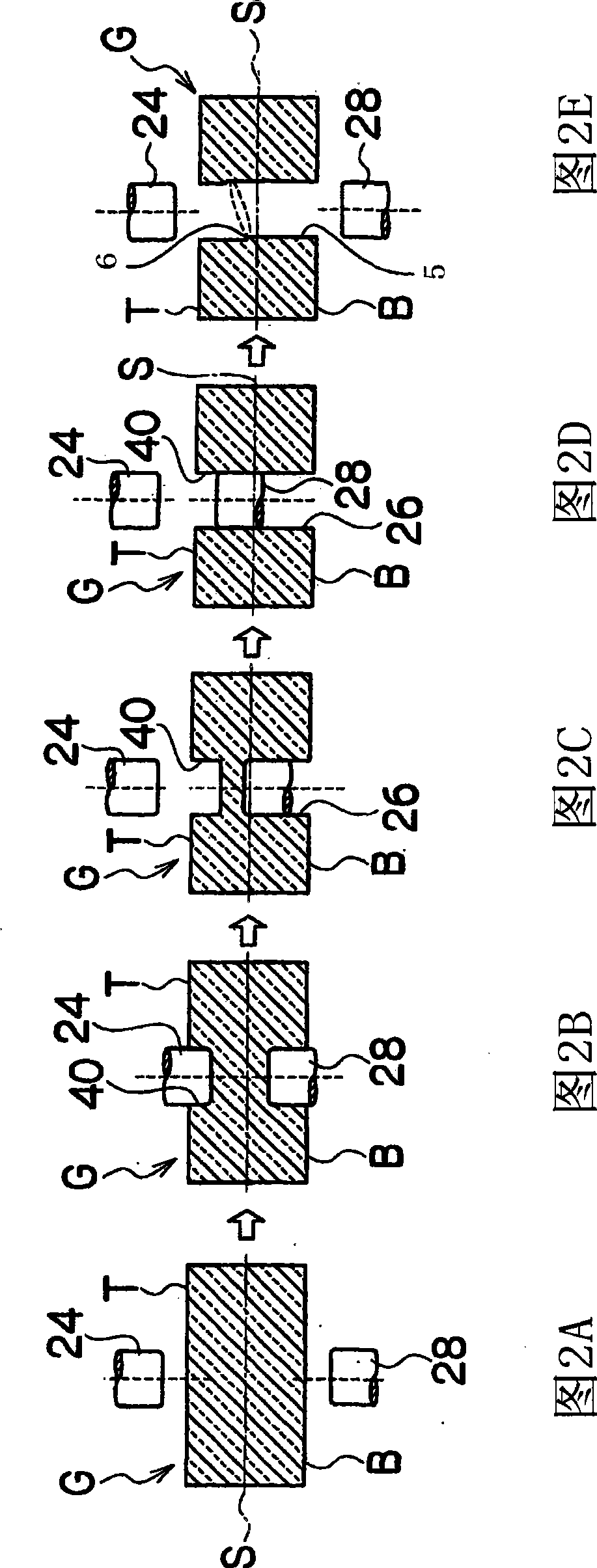
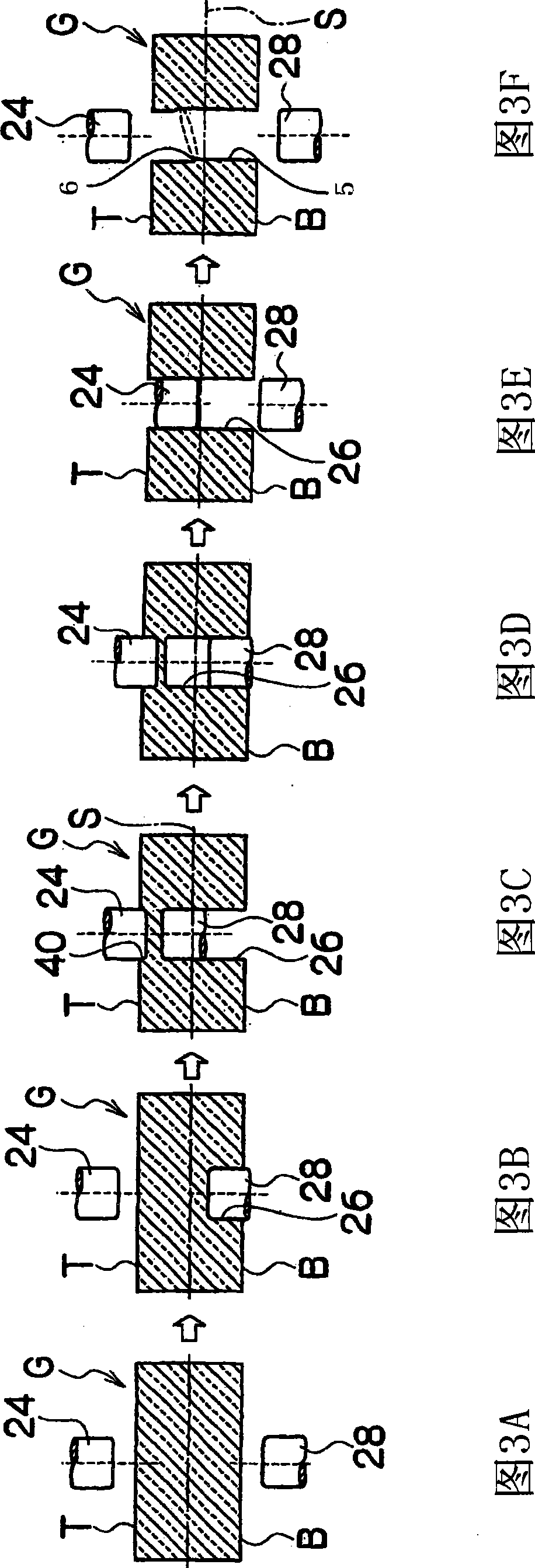
[0050] A total of 60 samples were prepared by opening through-holes having a diameter of 2 mm at positions 11.5 mm apart from respective two right-angled end faces of a substantially rectangular PDP glass substrate G measuring 150 mm by 150 mm and having a thickness of 1.8 mm, where the step 6 appearing on the through hole 5 is formed at a position separated from the bottom surface B of the glass substrate G by 1.7 mm. In seven of the above-mentioned samples, the steps 6 were formed at intervals of 0.1 mm from positions 1.7 mm to 1.0 mm from the bottom surface. In four samples of the above samples, the step 6 was formed at a position of 0.9 mm from the bottom surface B of the glass substrate G. As shown in FIG. For the above samples, the glass substrate G was heated for 10 minutes (approximately 280 degrees: where a temperature difference of approximately 170 degrees between the top and bottom surfaces was achieved), while the bottom surface B was placed in a heated On the de...


PUM

PropertyMeasurementUnit
thicknessaaaaaaaaaa
thicknessaaaaaaaaaa
thicknessaaaaaaaaaa

Abstract

A first hole of a predetermined depth is formed in a glass substrate by pressing a first drill against the lower surface of the glass substrate while rotating the first drill. A second hole is formed in the glass substrate by pressing a second drill against the upper surface of the glass substrate at the position facing the first hole while rotating the second drill. A through-hole is formed in the glass substrate by connecting the first hole with the second hole. Since the first and second holes are overlapped with each other in the thickness direction of the glass substrate, a step part formed on the inner peripheral part of the through hole is positioned on the upper surface side higher than the center of the glass substrate in the thickness direction.

Description

technical field [0001] The present invention relates to a method for drilling a glass substrate and a glass substrate for a plasma display produced by the method; in particular, to a method for use in two pieces of glass to be assembled into a plasma display A glass substrate drilling method for making through holes for exhaust purposes in the rear side glass substrate in the substrate, and glass substrates for plasma displays. Background technique [0002] By sealing two glass substrates with a sealant and filling the inside of the sealed glass substrates with a discharge gas, a plasma display (hereinafter, plasma display panel abbreviated as "PDP") as a light-emitting direct-view display is manufactured in an ultra-thin and large A display for a flat-screen TV that consists of a front glass substrate and a rear glass substrate. In the front glass substrate, a transparent dielectric and a MgO protective layer were formed over the display electrodes for discharge. In the r...

Claims


Application Information

Patent Timeline
Patent Type & Authority Applications(China)
IPC IPC(8): B28D1/14H01J11/02
CPCB28D1/14H01J9/241H01J9/385Y10T408/03Y10T428/24273B26F1/16H01J11/34
Inventor 花田彰太郎郑盛吉
Owner ASAHI GLASS CO LTD
Why Eureka
Try Eureka