
Seal system in particular for joint connections on hot gas flow paths

A sealing system and flow path technology, which is applied in the direction of engine sealing, exhaust device, muffler device, etc., can solve problems such as mechanical weakening, and achieve the effect of simple assembly process and reduced manufacturing cost.

Inactive Publication Date: 2009-09-02
ELRINGKLINGER AG
View PDF0 Cites 3 Cited by
  • Summary
  • Abstract
  • Description
  • Claims
  • Application Information

AI Technical Summary

Problems solved by technology

Such a construction not only entails a significant manufacturing effort, but also a mechanical weakening of the associated connecting parts.

Method used


Image

  • Seal system in particular for joint connections on hot gas flow paths
  • Seal system in particular for joint connections on hot gas flow paths
  • Seal system in particular for joint connections on hot gas flow paths

Examples


Embodiment Construction

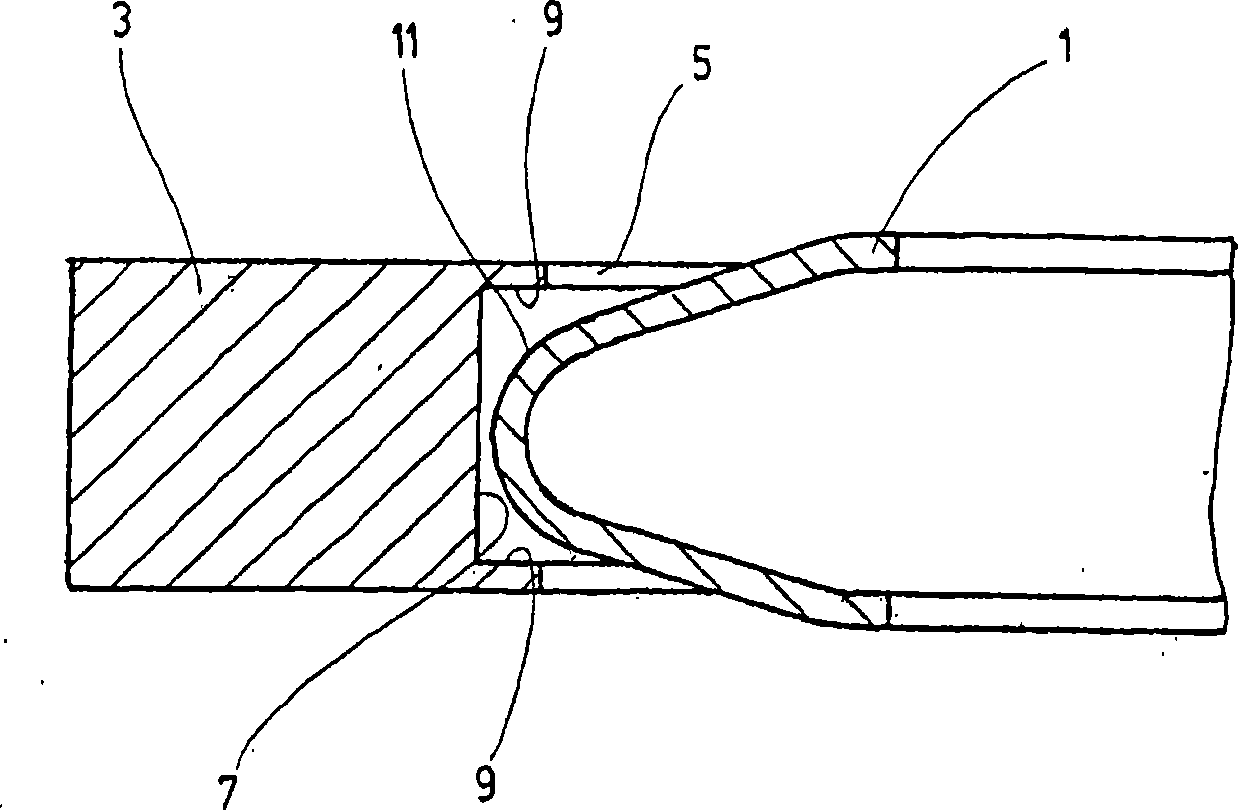
[0025] exist figure 1 The vertically arranged axis extensions shown in 5 to 20 relate to the longitudinal axis of the respective flow path to be sealed.

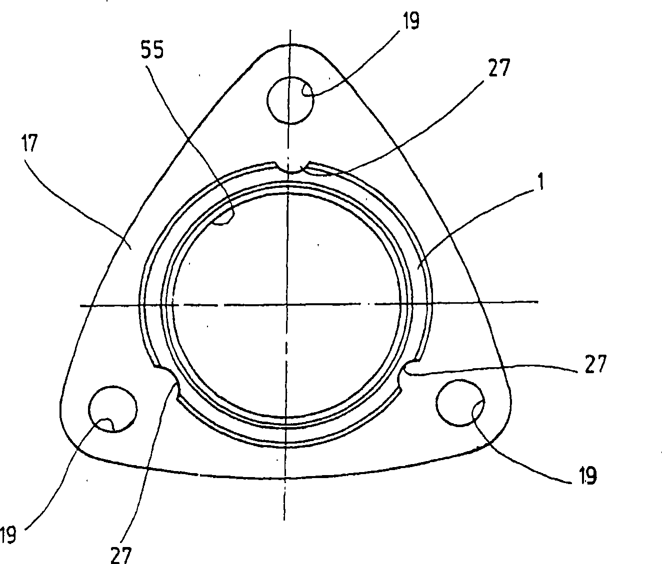
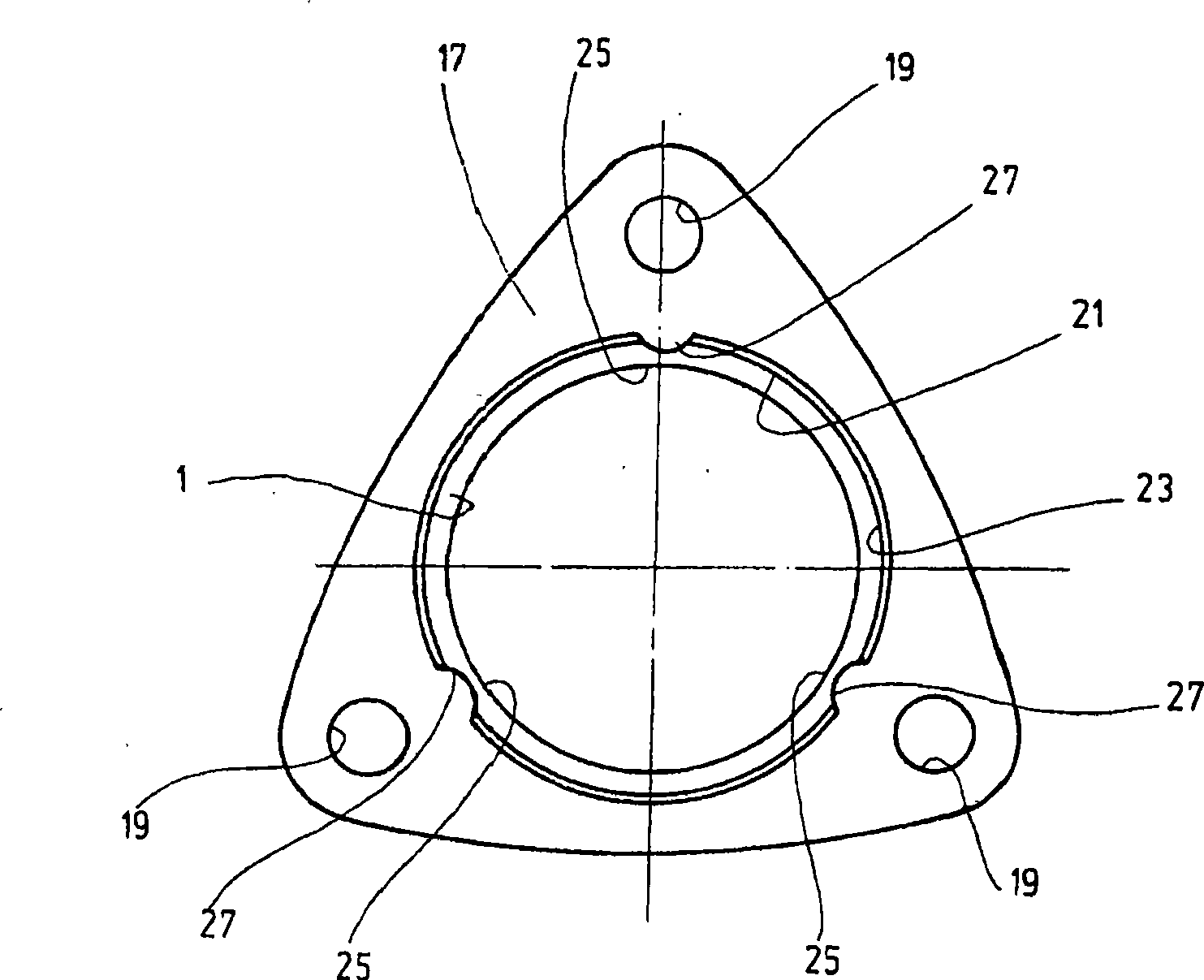
[0026] figure 1 A first exemplary embodiment of the sealing system is shown, in which only the connection region between the seal seat and the sealing element in the form of a metallic profile ring 1 is shown in a partial longitudinal section shown broken and drawn to an exaggeratedly large scale , which relates to a one-piece shaped body whose profile has a V-shaped cross-sectional shape. The forming ring 1 is arranged in a sealing seat, which has the shape of a circular metal ring body 3, which can be fixed between the not shown connectors of the relevant interface connection device, so that it is in contact with the forming ring. 1 together form a flow path for a hot gas such as an exhaust gas flow. On its radially inner annular edge 5, the annular body 3 has a seat for the forming ring 1, wherein figure 1 In the exam...


PUM


Abstract

The invention relates to a seal system, in particular, for joint connections on hot gas flow paths, such as exhaust systems on internal combustion engines, comprising a seal support (3) and at least one seal element (1) defining a seal plane lying between sealing surfaces, characterised in that the seal support (3) is a separate component from the seal element (1) as a further separate component and that in order to obtain the seal system both components are non-detachably connected to each other.

Description

technical field [0001] The invention relates to a sealing system, in particular for an interface connection on a flow path of a hot gas, such as an exhaust gas flow of an internal combustion engine, comprising a sealing seat and at least one sealing element defining a sealing plane between sealing surfaces . Background technique [0002] Interface connections to be sealed in the area of ​​hot gases, such as in internal combustion engines, for example at the manifold outlet, at the turbocharger, at the catalytic converter or also in the connection area between the cylinder head and the exhaust gas manifold In this case, high thermal and mechanical loads occur, so that a high structural outlay is required for the associated sealing system. Metal seals made of heat-resistant alloy materials must be used as sealing elements, wherein the exhaust gas-conducting connecting parts must have a groove or a step for an associated annular sealing element in their function as a sealing s...

Claims


Application Information

Patent Timeline
Patent Type & Authority Applications(China)
IPC IPC(8): F16J15/08F01N7/18F16L23/20F01N13/16F01N13/18
CPCF01N13/1827F16J15/0887
Inventor W·库伦M·克尔K·施文克尔E·格里辛格A·伦纳特P·布劳恩R·沃尔夫
Owner ELRINGKLINGER AG
Learn More