Rectangular open magnetic field type electromagnetic vibration table magnetic circuit structure with double-magnetic-circuit two-end symmetric excitation

An electromagnetic vibration, dual magnetic circuit technology, applied in vibration testing, fluid using vibration, testing of machine/structural components, etc., can solve the problems of difficult processing and assembly of permanent magnets, difficult to guarantee assembly accuracy, and limited magnetization effect. , to easily ensure the accuracy of processing and assembly, reduce the difficulty of processing and assembly, and achieve the effect of simple and reliable magnetic circuit structure

Active Publication Date: 2015-08-19
HARBIN INST OF TECH
View PDF6 Cites 2 Cited by
  • Summary
  • Abstract
  • Description
  • Claims
  • Application Information

AI Technical Summary

Problems solved by technology

[0005] The disadvantages of the above two technical solutions are: 1) the cylindrical outer yoke needs to be processed in the long inner dimension, which is difficult to process and difficult to guarantee the accuracy; 2) when the cylindrical permanent magnet is used, the through hole needs to be processed on the permanent magnet And it is fixed on the yoke by non-magnetic bolts, the assembly is complicated and will affect the magnetic circuit; when a cylindrical permanent magnet is used, it is difficult to sinter, process, magnetize and assemble a large-sized cylindrical permanent magnet; 3) The cylindrical outer yoke needs to be set on the central yoke. If the permanent magnet is magnetized first and then assembled, the assembly is very difficult and the assembly accuracy is difficult to guarantee; the permanent magnet of AlNiCo material can be assembled first and then magnetized. However, due to the low coercive force of the permanent magnet of the AlNiCo material, the magnetization effect is limited and the performance is not good, which seriously restricts the mechanical properties and indicators of the magnetic circuit structure.
[0007] The disadvantages of this technical solution are: 1) the entire magnetic circuit structure is composed of multiple structural combinations and splicing, and the structure is complex; the small permanent magnet needs to be installed on the wedge-shaped pole piece by gluing or other methods, which is complicated to assemble and difficult to ensure. Assembly accuracy; 2) The static magnetic induction intensity at a certain position in the air gap is directly related to the working point of the permanent magnet at that position, and the uniformity of the magnetic field in the entire air gap is difficult to guarantee, and the consistency of materials and processes for small permanent magnets is required Higher; 3) The permanent magnet directly faces the air gap, and the additional magnetic field generated after the working coil is energized will force it to be magnetized or demagnetized. When a large current is passed through the working coil, it is easy to cause irreversible demagnetization of the permanent magnet; 4) When the working coil is energized, the magnetic flux on one side of the coil increases and the magnetic flux on the other side decreases. Since the permanent magnet directly faces the air gap, the magnetic circuit on the side where the magnetic flux increases is easy to saturate. At this time, one side of the coil increases The magnetic flux of the coil is less than the reduced flux of the other side, resulting in a decrease in the average magnetic induction intensity at the position of the coil, which in turn distorts the generated standard vibration signal
However, there are various problems and deficiencies in the existing technologies. It is difficult to further improve the uniformity of the static magnetic induction intensity distribution in the air gap and the linearity index of the output electromagnetic driving force after the coil is energized.
[0009] There are three key issues: (1) The uniformity of the magnetic induction intensity distribution of the main magnetic circuit in the long air gap is difficult to guarantee
Before the coil is energized, the permanent magnet is excited to form the magnetic induction intensity distribution of the main magnetic circuit. With the increase of the stroke of the electromagnetic vibrating table, the problem of non-uniformity of the magnetic field in the long air gap becomes very prominent, which seriously restricts the output of the electromagnetic driving force after the coil is energized. linearity; some researchers try to compensate by adjusting the current waveform, but the effect is difficult to guarantee, especially for high-order magnetic field non-uniformity error compensation effect is poor, so far no truly effective and highly practical compensation has been proposed at home and abroad method
(2) The influence of the armature reaction after the working coil is energized
(3) It is difficult to process and assemble long yokes and large-size permanent magnets, and the accuracy is difficult to guarantee
[0011] In summary, restricted by the above problems, the standard low-frequency vibration produced by existing technical solutions is difficult to make breakthroughs in indicators such as waveform distortion, and it is difficult to meet the high-precision calibration of low-frequency / ultra-low-frequency vibration, especially the next generation with very low frequency and the need for vibration calibration of ultra-precise features

Method used


Image

  • Rectangular open magnetic field type electromagnetic vibration table magnetic circuit structure with double-magnetic-circuit two-end symmetric excitation
  • Rectangular open magnetic field type electromagnetic vibration table magnetic circuit structure with double-magnetic-circuit two-end symmetric excitation
  • Rectangular open magnetic field type electromagnetic vibration table magnetic circuit structure with double-magnetic-circuit two-end symmetric excitation

Examples


Embodiment Construction

[0040] The specific implementation manner of the present invention will be described in detail below with reference to the accompanying drawings, and examples will be given.

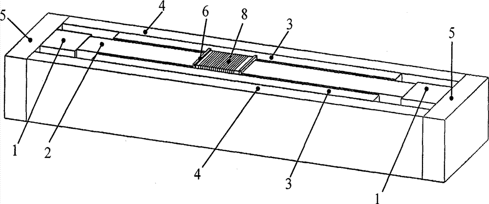
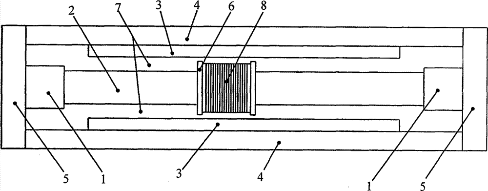
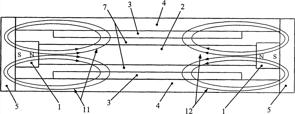
[0041] A rectangular open magnetic field type electromagnetic vibrating table magnetic circuit structure with symmetrical excitation at both ends of the double magnetic circuit, consisting of a permanent magnet 1, a central yoke 2, an inner yoke 3, an outer yoke 4, an end yoke 5, a coil bobbin 6 and The working coil 8 is composed of an axisymmetric structure as a whole. The cross-sections of the permanent magnet 1, the central yoke 2, the inner yoke 3, the outer yoke 4 and the end yoke 5 are all rectangular, and the cross-section of the coil bobbin 6 is square. The two ends of an outer yoke 4 are respectively rigidly connected with two end yokes 5 to form a square-shaped yoke structure. The central yoke 2 is installed on the long axis of the square-shaped yoke structure, and the length of the inner yoke 3...


PUM


Abstract

The invention provides a rectangular open magnetic field type electromagnetic vibration table magnetic circuit structure with double-magnetic-circuit two-end symmetric excitation, belonging to the field of vibration measurement technology. A rectangular open type magnetic field structure design is provided. Two permanent magnets are symmetrically installed at two ends of a center magnet yoke and face magnetic poles. Two symmetric closed magnetic circuits are formed by magnet yokes. The magnetic induction intensity distribution with high uniformity is generated in air gaps. After a working coil is energized, the working coil is affected by Lorentz force in a magnetic field, and precisely controllable electromagnetic drive force is generated. The surfaces of the magnet yokes adjacent to the air gaps are provided with an array type micro structure in the form of deep trenches, and the eddy current loss can be effectively inhibited. According to the rectangular open magnetic field type electromagnetic vibration table magnetic circuit structure, large stroke, high magnetic field uniformity, high thrust and a linear electromagnetic driving force characteristic can be considered, the disadvantages in the existing technical scheme can be effectively solved, and a high precision and large stroke electromagnetic vibration table magnetic circuit structure technical scheme is provided for low-frequency/ultra-low frequency vibration calibration.

Description

technical field [0001] The invention belongs to the technical field of vibration measurement, and mainly relates to a magnetic circuit structure of a rectangular open magnetic field type electromagnetic vibrating table with symmetrical excitation at both ends of a double magnetic circuit. Background technique [0002] The electromagnetic vibrating table that generates standard vibration signals is the key equipment for high-precision vibration calibration and an important part of the national vibration measurement technology system. The magnetic circuit structure is the core key component of the electromagnetic vibrating table. It is generally composed of a permanent magnet, a yoke, a coil skeleton and a working coil. The permanent magnet and the yoke form a magnetic circuit, which generates a highly uniform magnetic field distribution in the air gap. After the coil is energized, it is subjected to the Lorentz force in the magnetic field, thereby generating a precise and con...

Claims


Application Information

Patent Timeline
Patent Type & Authority Applications(China)
IPC IPC(8): G01M7/02B06B1/04
Inventor 谭久彬何张强崔俊宁
Owner HARBIN INST OF TECH
Why Eureka
Try Eureka