Eureka AIR delivers breakthrough ideas for toughest innovation challenges, trusted by R&D personnel around the world.

Smelt spout enclosure for chemical recovery boilers

A technology of chemical recovery and melting, applied in incinerators, combustion methods, lighting and heating equipment, etc., can solve the problems of capacity overload, inability to be properly washed again, and reduction of reduction efficiency

Inactive Publication Date: 2009-09-02
GENERAL ELECTRIC TECH GMBH
View PDF0 Cites 4 Cited by
  • Summary
  • Abstract
  • Description
  • Claims
  • Application Information

AI Technical Summary

Problems solved by technology

This curvature disrupts the baffle action of the initial wash system and if allowed to continue, the area will not be able to be properly washed again until the side panel walls straighten
Another effect of this situation is that locally higher temperatures can accelerate the corrosion of the side wall
Fluid air ensues and, either distorts the smelt flow from the chute, which tends to re-oxidize the smelt (reducing reduction efficiency), or can overload the capacity of the scrubber exhaust that would allow gases to escape from the dissolution tank into the working environment

Method used


Image

  • Smelt spout enclosure for chemical recovery boilers
  • Smelt spout enclosure for chemical recovery boilers
  • Smelt spout enclosure for chemical recovery boilers

Examples


Embodiment Construction

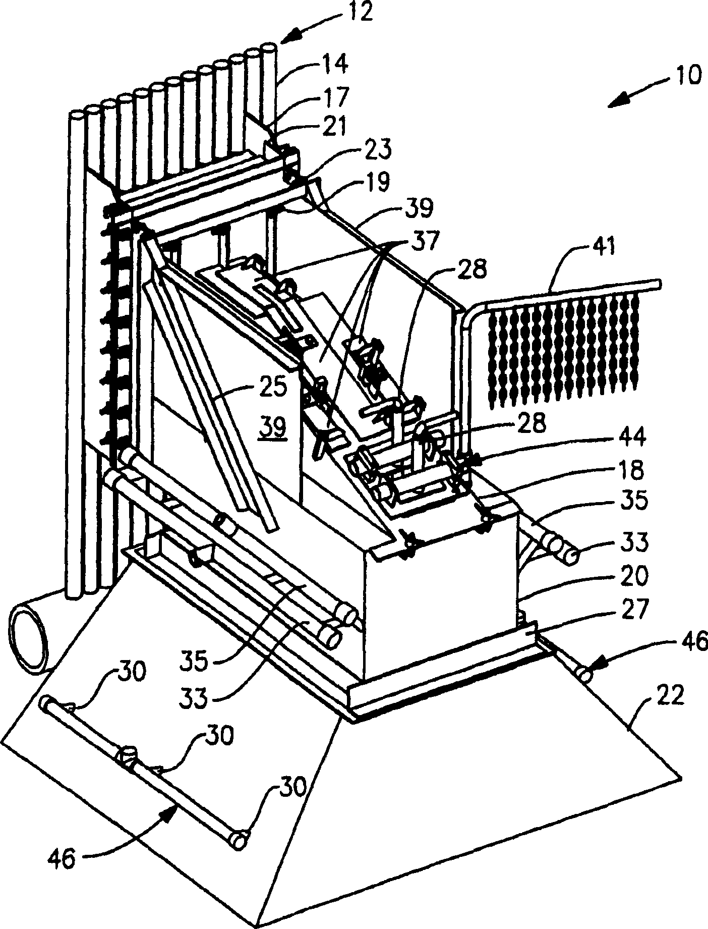
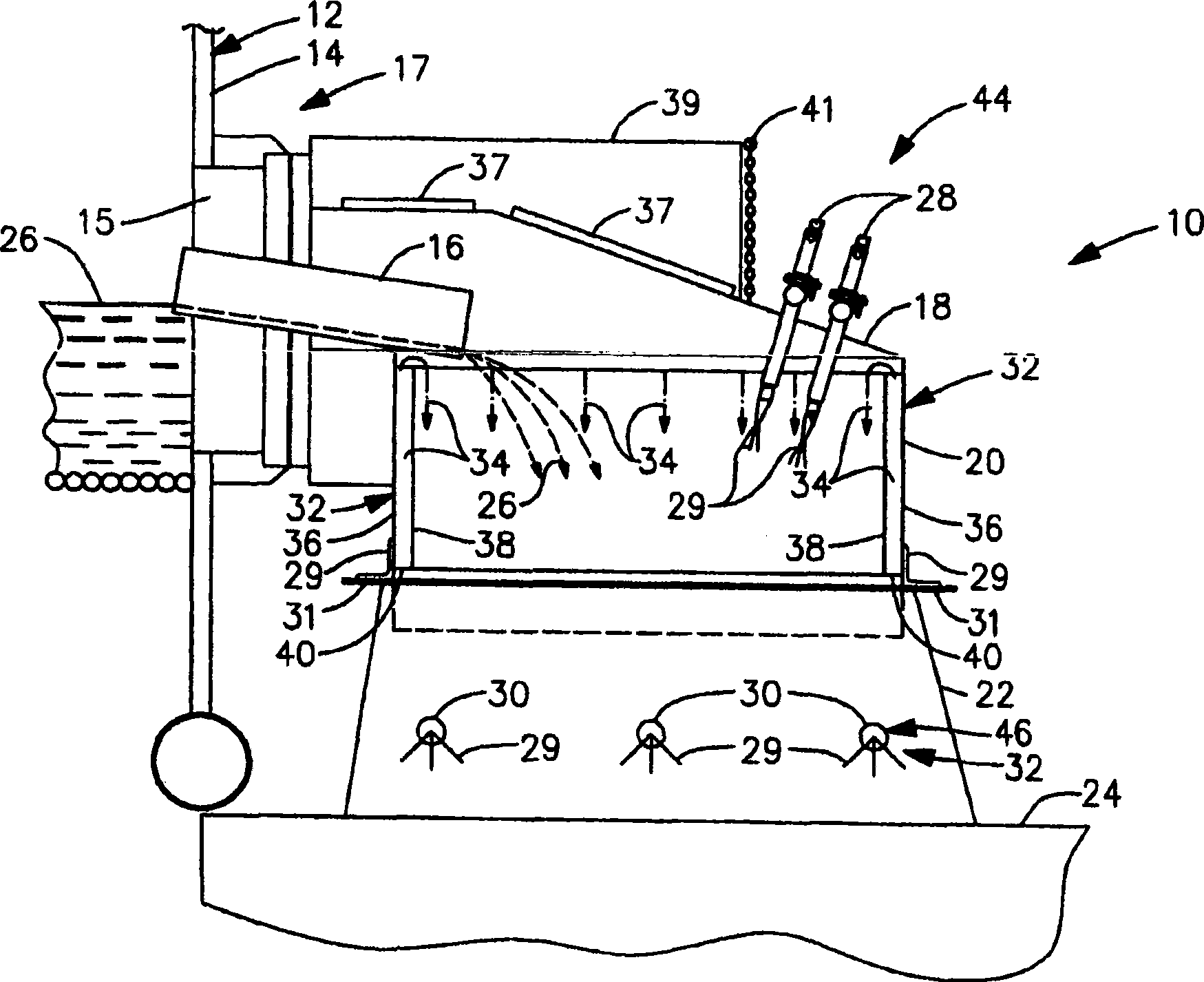
[0021] 【0021】 figure 1 is a perspective view of the smelt chute housing 10 attached to the wall of a conventional chemical recovery boiler 12; and figure 2 is a simplified cross-sectional view of the smelt spout housing 10 . refer to figure 1 and 2 The walls of the recovery boiler 12 are formed by water-cooled tubes 14 shaped to provide openings 15 above the bottom of the furnace section of the boiler 12 . A smelt spout 16 extends through the opening 15 . The portion of the smelt chute 16 which extends outside the boiler 12 is surrounded by an enclosure 10 to prevent splashing of fluid and smelt and discharge of exhaust gases to the surrounding environment. The lower end of the housing 10 is arranged in an opening in the extension 22 of the dissolution tank 24 .

[0022] [0022] Hot, fluid melt 26 flows from the bottom of the furnace portion of boiler 12 through opening 15 to melt chute 16. The melt 26 flows along the bottom of the chute 16 and falls from the free end of...


PUM


Abstract

An enclosure (10) for a smelt spout (16) of a chemical recovery boiler comprises a skirt (20) having a central region through which smelt (26) flowing from the smelt spout (16) falls in route to a dissolving tank (24). The central region is defined by a wall (38) and has a trough (32) disposed around its perimeter. The trough (32) is supplied with a fluid (34) that overflows the trough (32) and flows downward across the wall (38) toward the dissolving tank (24) to clean and cool the central region of the skirt (20). A hood cover (18) has a pair of shields (39) disposed on opposite sides of rodding doors (37) and a chain curtain (41) extending between the pair of shields (39) to deflect smelt particles ejected through the rodding doors (37). A primary nozzle system (44) is configured to direct at least one shatter jet (29) onto the smelt (26) flowing from the smelt spout (16). In addition, a secondary nozzle system (46) is configured to direct a plurality of interlaced shatter jets (29) onto the smelt (26).

Description

Background technique [0001] [0001] Chemical recovery boilers perform two basic functions: burning organic matter to make steam for the various milling processes and recovering inorganic chemical materials for the pulping process. Processed inorganic chemical material or "melt" from the recovery boiler collects at the bottom of the furnace and is discharged into the main dissolution tank through a dedicated opening in the lower part of the furnace. The main dissolution tank is filled with waste water from the stucco washing process, also known as thin wash liquor. The molten smelt, with temperatures as high as 1500°F, must be broken up into small droplets using steam or jets of dilute scrubbing liquid before the molten smelt enters the main dissolution tank. If the melt is not comminuted properly, there will be an explosive reaction with the water in the dilute wash solution in the dissolution tank. In the dissolution tank, during start-up, the melt is dissolved into either w...

Claims


Application Information

Patent Timeline
IPC IPC(8): F23G7/04F23J1/08
CPCF23G7/04F23J1/08
Inventor S·R·吉波夫斯基
Owner GENERAL ELECTRIC TECH GMBH
Why Eureka
Eureka Blog
Learn More