Compact multi-band direction-finding antenna system

a multi-band direction-finding and antenna system technology, applied in the direction of resonant antennas, elongated active element feeds, independent non-interacting antenna combinations, etc., can solve the problem of large size, unreliable calibration and/or ambiguity of direction/azimuth in regard to transmitted signals, and degraded performance. problem, to achieve the effect of reducing the overall weight of the overall antenna system

Inactive Publication Date: 2002-11-12
LOCKHEED MARTIN CORP
View PDF14 Cites 160 Cited by
  • Summary
  • Abstract
  • Description
  • Claims
  • Application Information

AI Technical Summary

Problems solved by technology

Performance can also be degraded by adverse mast resonance effects caused by common mode coupling of antenna subsystem elements to the mast.
This mast resonance effect, if not controlled could cause dramatic phase change with relatively small frequency change that results in unreliable calibration and/or ambiguity of direction/azimuth in regard to the transmitted signal.
Large size also often implies significant weight of the overall antenna system.
Since many direction finding applications involve vehicles which must carry the antenna system, practical limitations on both size and weight may be imposed.
Further, land vehicles used in such applications are often operated in off-road environments where large antenna system size also implies an increased susceptibility to damage (e.g. from tree limbs and the like).
Additionally, the antenna system and its components will exhibit degradation in performance due to temperature variation, particularly extreme temperature rise due to solar loading.
Even relatively compact antenna designs which are known may be of substantial size.
For example,...

Method used


Image

  • Compact multi-band direction-finding antenna system
  • Compact multi-band direction-finding antenna system
  • Compact multi-band direction-finding antenna system

Examples


Embodiment Construction

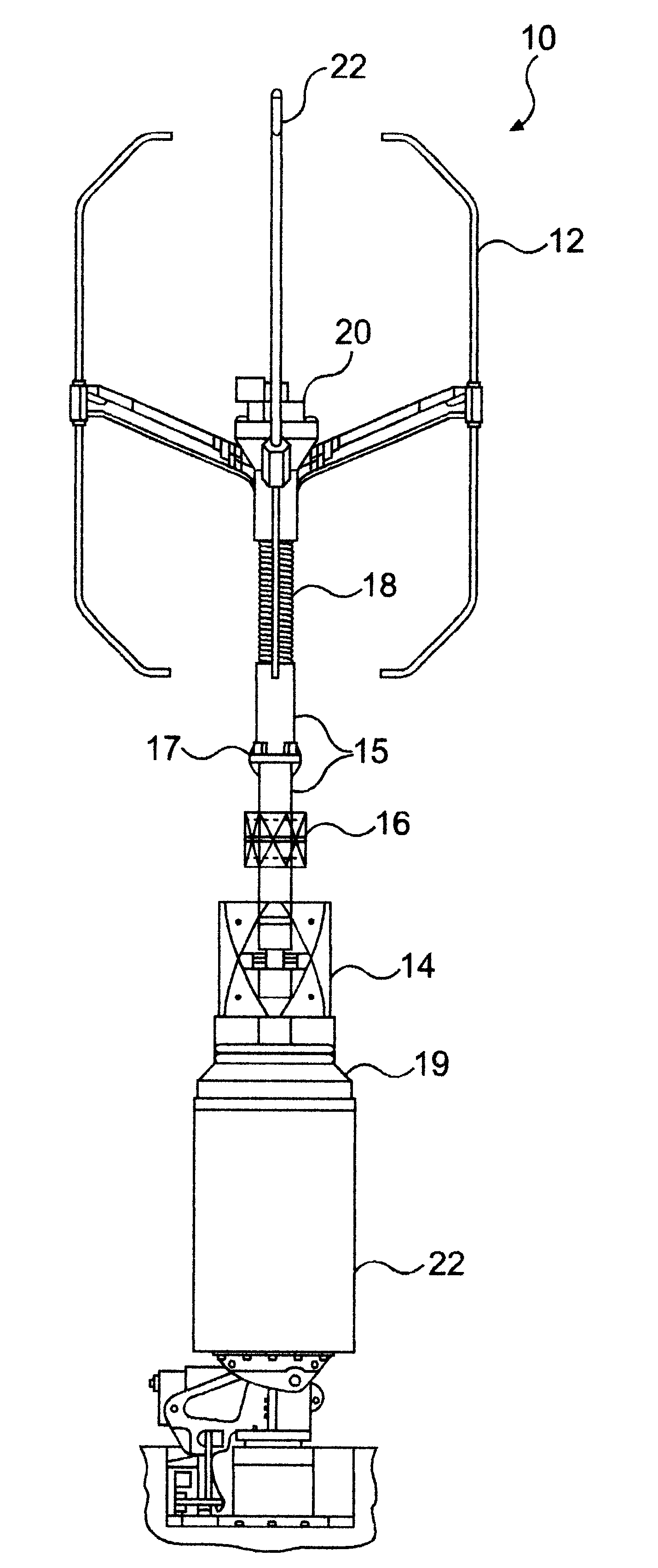
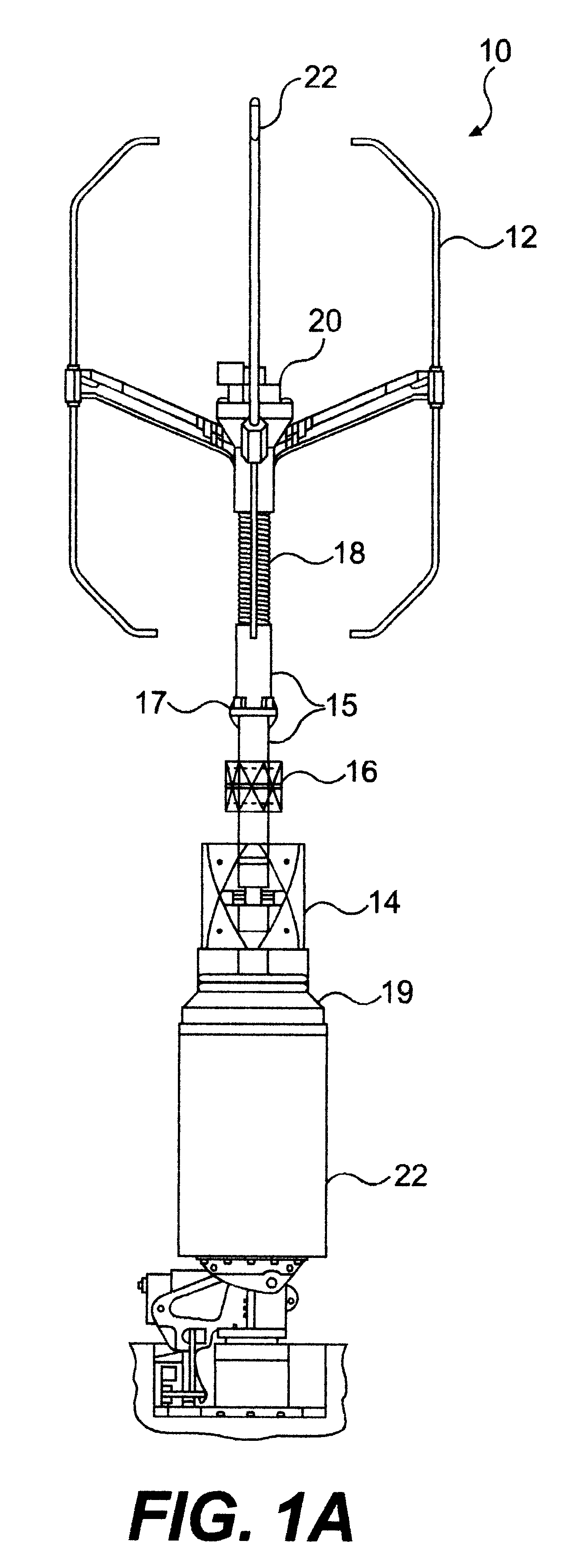
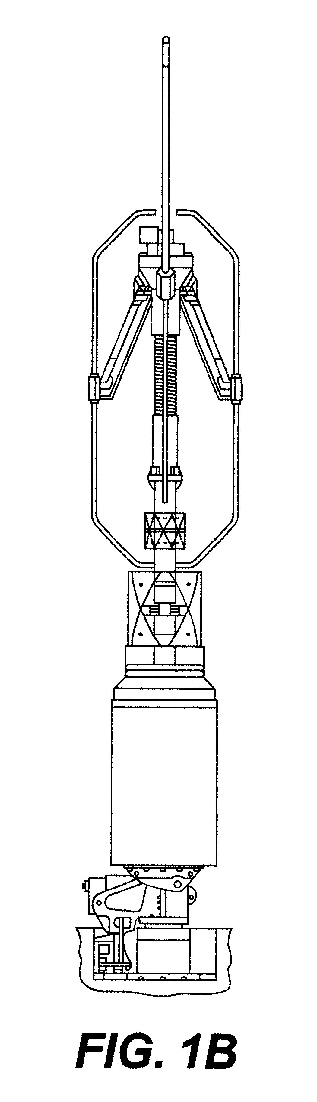
Referring now to the drawings, and more particularly to FIG. 1A, there is shown a side view of the antenna system 10 in accordance with the invention with the VHF section 12 in a deployed position. While this antenna system of the invention is quite compact, it is a feature of the invention that the largest (VHF) array 12 can be retracted for further reduction in the overall size of the antenna system in both height of the VHF dipoles and overall diameter, as shown in FIG. 1B to reduce likelihood of damage to the VHF dipole elements 12. It should be noted that when the VHF elements are retracted, a cage is formed around the SHF array 16 to reduce the likelihood of physical damage thereto. Further, the angle of the VHF dipole support to the horizontal, particularly in the retracted position provides substantial vibration and shock damping which can be augmented by additional damping in the actuator 20. A locking device which will be described below provides alignment of the asymmetri...


PUM


Abstract

An compact and rugged antenna system particularly suited to direction finding includes a plurality of antenna arrays for receiving respective frequency bands and colocated on a mast with separation between antenna arrays along the mast. The mast includes a coil wound of an insulator and functioning as a loaded inductor to shift the mast resonance out of the frequency band of the antenna system. A VHF dipole array having elements shaped to reduce scattering to UHF and SHF arrays is supported on movable arms which allow retraction that reduces height and provides mechanical protection to one or more other arrays as well as damping against vibration by contacting the mast with shaped portions of the dipole elements. The bowtie elements of the UHF array are angled at a central region to optimize array diameter at low UHF frequencies. A finned RF electronics housing is preferably provided which reduces solar loading and dissipates heat from antenna electronics. Asymmetrically keyed fittings are provided to permit accurate antenna system, array and element positioning and replaceable components and wiring, both internally and externally of the housing, is held in position to allow field repairs without recalibration.

Description

1. Field of the InventionThe present invention generally relates to multi-band radio antennas and, more particularly, to direction finding antennas which are compact and suitable for use on vehicles under adverse conditions.2. Description of the Prior ArtWireless communications are currently used for many applications including data transmission, resource tracking, and emergency or safety services. Many of these applications involve determining the location or the direction of a transmitter of radio frequency signals which may be of any frequency over a broad spectrum. However, antenna efficiency and directional selectivity are dependent on the relationship of the frequency of the radio carrier signal and the dimensions of the antenna elements and the distances between them and, in general, efficiency of a given antenna system will be acceptable only over a relatively limited band of frequencies.Therefore, multiple frequency band antenna subsystems are typically used to cover wide f...

Claims


Application Information

Patent Timeline
IPC IPC(8): H01Q1/12H01Q21/28H01Q1/52H01Q9/04H01Q1/32H01Q9/18H01Q21/00H01Q1/00
CPCH01Q1/1235H01Q1/1242H01Q1/32H01Q1/52H01Q9/18H01Q21/28
Inventor LAM, TOMMYLAVELLE, PAUL R.LEE, KENNETH W.MILICIC, JR., MATTHEW J.PRITCHETT, D. MICHAEL
Owner LOCKHEED MARTIN CORP
Why Eureka
Try Eureka