
Optical transmission system and optical transmission control method

一种控制方法、光传输的技术,应用在概率的光传输系统领域,能够解决偏振模式色散抗扰性改善量有限、波形均衡机制技术困难、改善量不经常等问题,达到减少工作精力、降低操作成本、高服务可用性的效果

Inactive Publication Date: 2009-09-02
NEC CORP
View PDF2 Cites 12 Cited by
  • Summary
  • Abstract
  • Description
  • Claims
  • Application Information

AI Technical Summary

Problems solved by technology

[0007] However, since factors causing BER deterioration are not limited to polarization mode dispersion, the deterioration caused by polarization mode dispersion must be extracted from the amount of BER deterioration, and no such method is currently available
In other words, BER information cannot be used for correct polarization mode dispersion equalization control
Therefore, the waveform equalization mechanism currently involves technical difficulties
[0008] Also, the amount of improvement in polarization mode dispersion immunity for any of the above conventional techniques is limited and not always proportional to cost

Method used


Image

  • Optical transmission system and optical transmission control method
  • Optical transmission system and optical transmission control method
  • Optical transmission system and optical transmission control method

Examples


Embodiment approach 1

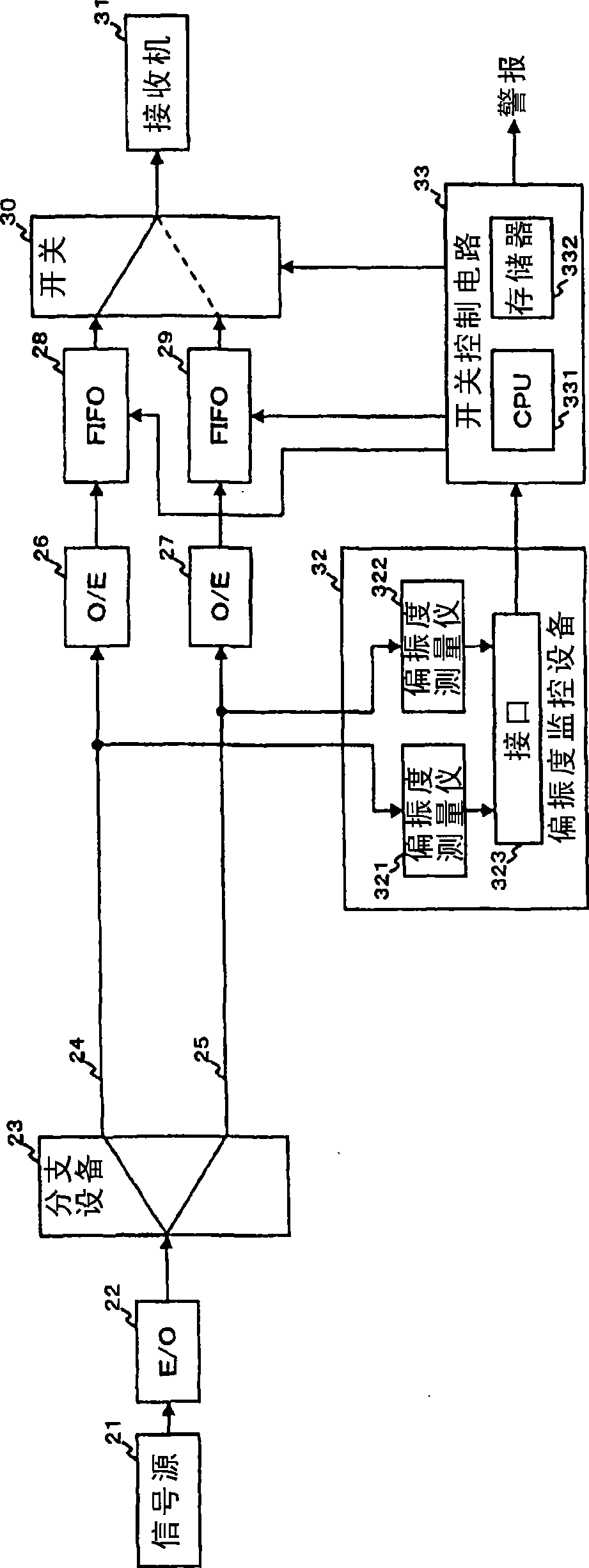
[0062] Below, will refer to figure 2 A specific exemplary embodiment of the present invention is described. figure 2 shows the use of figure 1 Exemplary implementations of the polarization mode dispersion monitoring device 9, the degree of polarization monitoring device 32, and the FIFO (first in first out) type electrical buffers 28, 29 for the buffers in the receiving unit.

[0063] exist figure 2 Among them, the transmission electrical signal generated from the signal source 21 is electro-optical converted by an electro-optical converter (E / O converter) 22, a 1:2 optical splitter (splitter) 23 is used as a branch device, and the optical transmission is multiplexed in two spaces The optical transmission channel 24,25 is performed.

[0064] The optical signals after transmission are photoelectrically converted by photoelectric converters (O / E converters) 26 , 27 , respectively, and input into FIFO type electrical buffers 28 , 29 .

[0065] The buffers 28, 29 can always...


PUM


Abstract

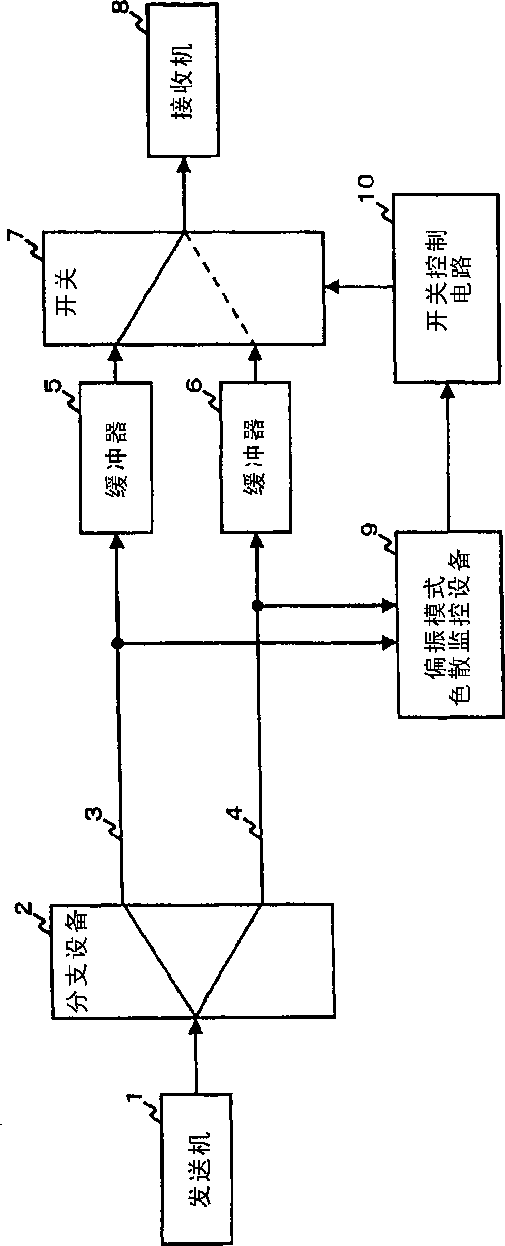
The invention provides an optical transmission system which is applicable not only to a known signal but also to an unknown signal, is low in cost, and has high reliability. A branching device branches the optical transmission output of a transmitter, transmits the branched signals over different optical transmission channels. A polarization mode dispersion monitor monitors the state of polarization mode dispersion from the optical transmission channels at the receiving end. A switch control circuit and a switch select a signal with smaller quality deterioration due to the polarization mode dispersion to output it to a receiver (8). This makes it possible to reduce the probability of the quality deterioration of a transmission signal due to polarization mode dispersion.

Description

technical field [0001] The present invention relates to an optical transmission system and an optical transmission control method, and more particularly, to an optical transmission system for reducing the probability of failure caused by polarization mode dispersion. Background technique [0002] In an optical transmission system, when a signal is transmitted at a relatively high rate on the order of tens of Gbps, the quality deterioration caused by polarization mode dispersion becomes non-negligible. As the influence of polarization mode dispersion increases, signals cannot be normally transmitted or received in some cases. The methods generally used to reduce the influence of polarization mode dispersion include: designing a transmission signal modulation mechanism, using a transmission channel less affected by polarization mode dispersion, and compensating for a distorted waveform. [0003] One way to design a modulation scheme for the transmitted signal is to use multi-...

Claims


Application Information

Patent Timeline
Patent Type & Authority Applications(China)
IPC IPC(8): H04B10/02H04B10/18H04B10/08H04B10/2569
CPCH04B10/2569
Inventor 竹下仁士伊东俊治
Owner NEC CORP
Learn More