

LED backlight module
A technology for a backlight module and an LED substrate, applied in the field of backlight modules, can solve the problems of cumbersome, serious, labor-consuming, etc., and achieve the effect of saving labor hours and being easy to assemble and disassemble
- Summary
- Abstract
- Description
- Claims
- Application Information
AI Technical Summary
Problems solved by technology
Method used
Image

Examples
Embodiment 1
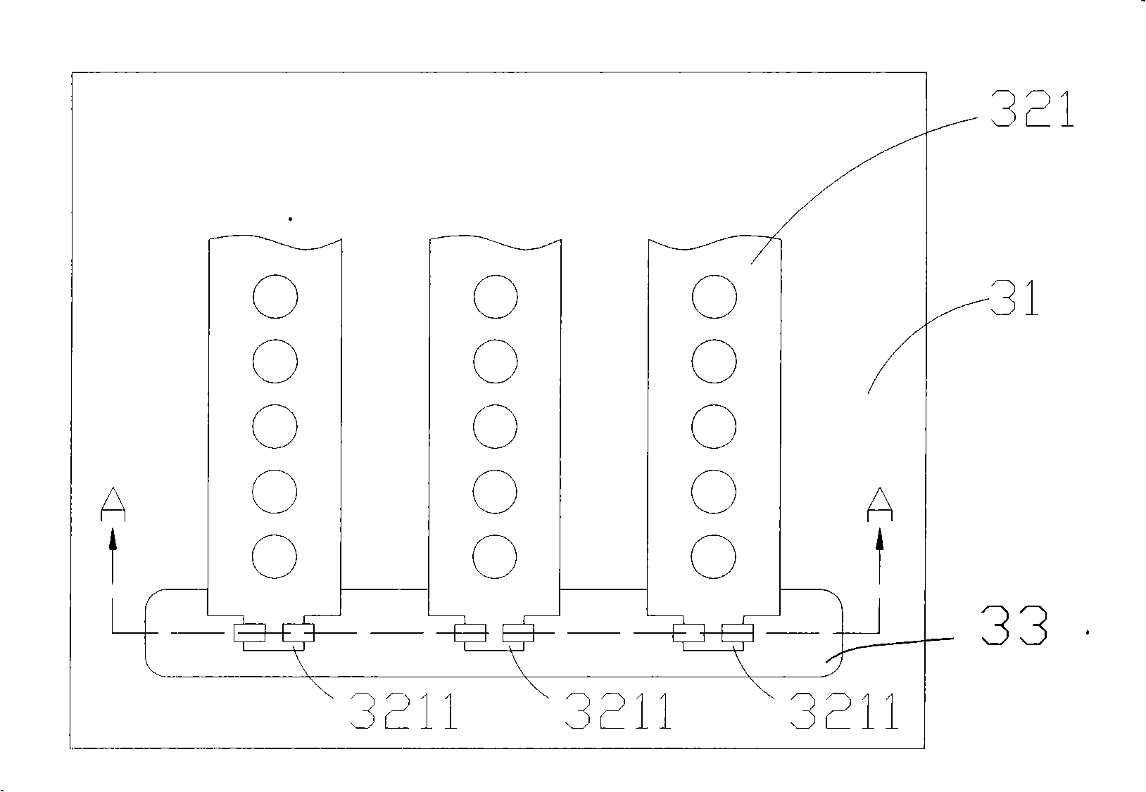
[0038] FIG. 3 is a schematic diagram of the fixing of the backlight module to the strip-shaped LED substrate of the present invention.
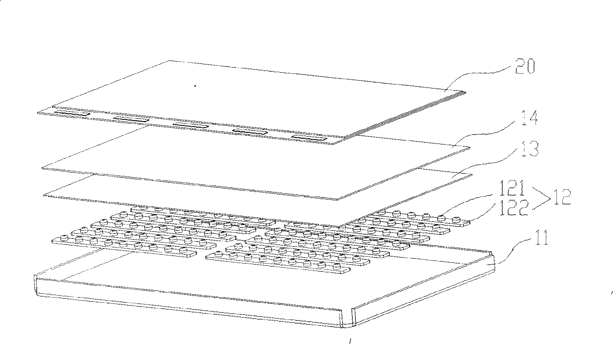
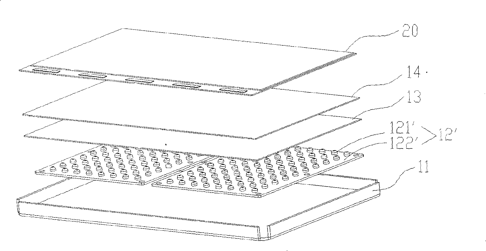
[0039] Figure 3A is the front view, Figure 3B for along Figure 3A The cross-sectional view of the A-A line in the middle, Figure 3A For the back view, this embodiment implements the fixing of the strip-shaped LED substrate. See Figure 3A , the LED backlight module in this embodiment includes a backboard 31; one or more LED lamp boards are placed on the backboard 31, and the LED lamp boards include an LED substrate 321 and a plurality of LED light sources; The light guide plate is placed on the LED substrate; wherein, the LED backlight module further includes a fixing part 33, a fixing groove 331 is formed on the front side of the fixing part 33, a mushroom-shaped hook 332 is formed on the back side, and the two sides of the LED substrate 321 There are two more protruding clamping ends 3211 on each side, so as to cooperate with the f...
Embodiment 2
[0041] FIG. 4 is another schematic diagram of fixing the backlight module to the strip-shaped LED substrate according to the present invention.
[0042] Please refer to Figure 4, Figure 4A is the front view, Figure 4B for along Figure 4A The cross-sectional view of the B-B line in the middle, Figure 4CFor the rear view, this embodiment provides another fixing method for the strip-shaped LED substrate. Compared with Embodiment 1, the reverse side of the fixing part 43 in this embodiment adopts a cylindrical protrusion 432, and a long perforation 412 is also used on the back plate 41 to cooperate with it. The long perforation 412 includes two through-connected long perforation start ends 4121 (bigger perforation) and strip perforation end 4122 (smaller perforation), when assembled, the cylindrical protrusion 432 extends into the larger perforation, that is, the beginning of the long perforation 4121, when the protrusion of the LED substrate 421 is clamped After the end 4...
Embodiment 3
[0044] FIG. 5 is a schematic diagram of fixing the backlight module of the present invention to a large LED substrate.
[0045] Please refer to Figure 5, Figure 5A is the front view, Figure 5B for along Figure 5A The cross-sectional view of the C-C line in the middle, Figure 5C It is a back view. In this embodiment, the large piece of LED substrate 521 is fixed. The front and back of the fixing part 53 are provided with mushroom-shaped hooks 531 and 532. When assembling, the mushroom-shaped hooks 532 on the back side of the fixing part 53 Extending into the circular perforation 512 fixed on the back plate, the large LED substrate 521 is also provided with a circular perforation and the mushroom-shaped hook 531 on the front of the fixing part 53 is fitted together. When assembling, it is only necessary to directly place the large LED substrate 521 is pressed down, and the mushroom-shaped hook 531 can securely fix the substrate. The disassembly of the substrate is the sa...
PUM
 Abstract
Description
Claims
Application Information