Stacked integrated circuit and manufacturing method thereof

一种集成电路、堆叠式的技术,应用在电路、半导体/固态器件制造、电气元件等方向,能够解决一般产品及方法没有适切结构及方法、不便等问题,达到产品可靠度改善、技术进步的效果

Active Publication Date: 2009-09-09
TAIWAN SEMICON MFG CO LTD
View PDF2 Cites 21 Cited by
  • Summary
  • Abstract
  • Description
  • Claims
  • Application Information

AI Technical Summary

Problems solved by technology

[0006] It can be seen that the above-mentioned existing integrated circuit and its manufacturing method obviously still have inconvenience and defects in product structure, manufacturing method and use, and need to be further improved urgently.
In order to solve the above-mentioned problems, the relevant manufacturers have tried their best to find a solution, but no suitable design has been developed for a long time, and there is no suitable structure and method for general products and methods to solve the above-mentioned problems. This is obviously a problem that relevant industry players are eager to solve

Method used

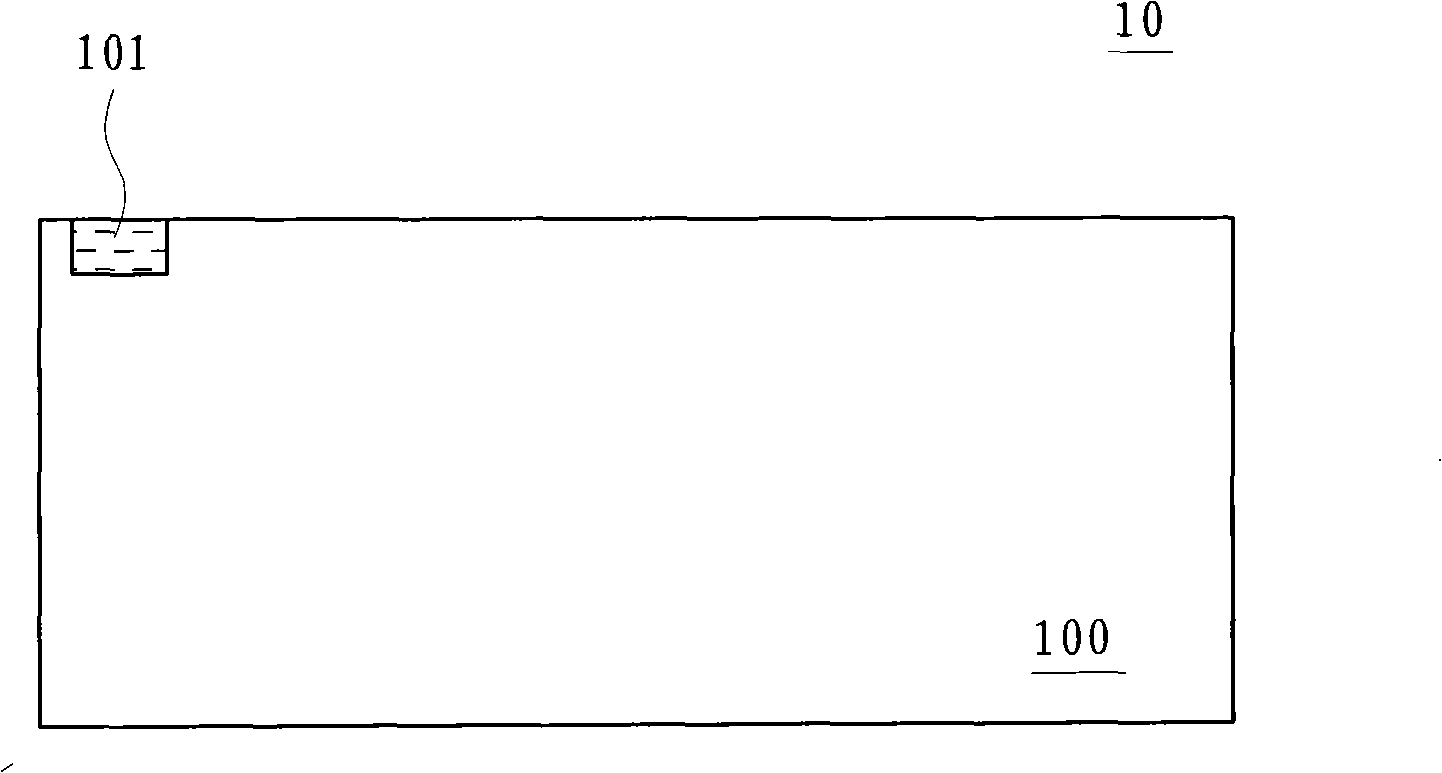
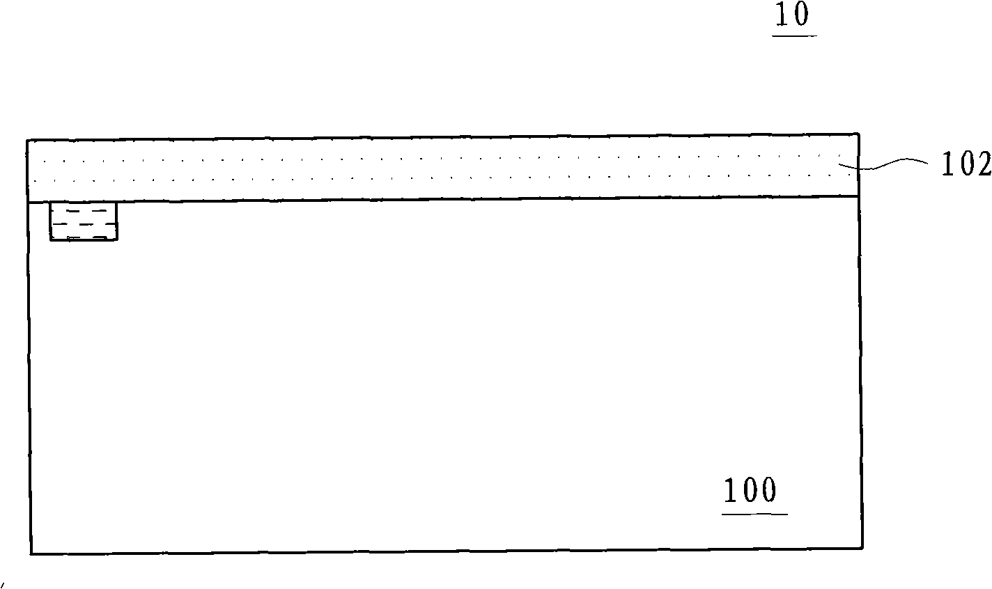
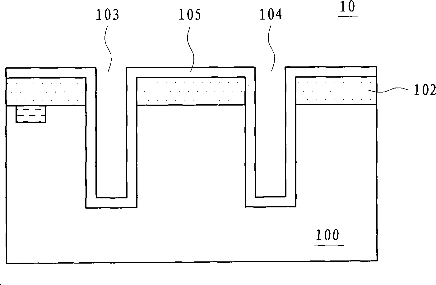

Image

  • Stacked integrated circuit and manufacturing method thereof
  • Stacked integrated circuit and manufacturing method thereof
  • Stacked integrated circuit and manufacturing method thereof

Examples


Embodiment Construction

[0087] In order to further explain the technical means and effects of the present invention to achieve the intended purpose of the invention, the specific implementation, structure and method of the stacked integrated circuit and its manufacturing method proposed according to the present invention will be described below in conjunction with the accompanying drawings and preferred embodiments. , steps, features and effects thereof are described in detail below.

[0088] The aforementioned and other technical contents, features and effects of the present invention will be clearly presented in the following detailed description of preferred embodiments with reference to the drawings. Through the description of the specific implementation mode, when the technical means and functions adopted by the present invention to achieve the predetermined purpose can be obtained a deeper and more specific understanding, but the accompanying drawings are only for reference and description, and ar...


PUM


Abstract

The present invention relates to a stacked integrated circuit and manufacturing method thereof. The formation of bonding pad protective layer over exposed bonding pad materials between stacked integrated circuit (IC) dies or wafers is described in preferred embodiments in which the bonding pad protective layer is formed in the integrated process of forming wafer bonding pads. The bonding pad protective layer prevents the exposed bonding pad materials from oxidation and corrosion in open-air or other harsh environments. By providing a bonding pad protective layer on exposed bonding pad materials, significant product reliability improvement is expected on ICs having a three-dimensional ''stacked-die'' configuration.

Description

technical field [0001] The present invention relates to the manufacture of an integrated circuit, in particular to a stacked integrated circuit and its manufacturing method related to the formation of protective layers for wafers and / or chip pads. Background technique [0002] In modern integrated circuits, the speed of operation on the integrated circuit is usually limited, among other things, by the farthest apart intercommunicating components on a chip (ie, a wafer, hereinafter referred to as a chip). As long as the vertical distance between the material layers is smaller than the chip width of the individual material layers, laying out the circuit as a three-dimensional structure has been shown to greatly shorten the communication paths of the components on the chip. Thus, by stacking circuit layers vertically, the overall chip speed is typically increased. The method that has been used to implement this stacking is through wafer bonding. [0003] Wafer bonding is usua...

Claims


Application Information

Patent Timeline
Patent Type & Authority Applications(China)
IPC IPC(8): H01L25/00H01L25/065H01L23/48H01L21/60
CPCH01L2224/05639H01L25/0657H01L2924/0105H01L2924/01082H01L2224/13025H01L2924/01049H01L2224/05624H01L2224/81054H01L2224/81203H01L2224/81801H01L24/13H01L2225/06541H01L2924/01029H01L2224/13147H01L2224/13099H01L2224/0401H01L2924/01027H01L2924/01013H01L2224/81894H01L25/50H01L24/81H01L24/06H01L2924/01047H01L2924/01079H01L24/16H01L2224/05647H01L2224/05684H01L2225/06513H01L2924/01033H01L24/11H01L2924/01006H01L2924/10329H01L21/76898H01L2224/06181H01L2224/8192H01L2924/01074H01L2924/01014H01L23/3171H01L2924/14H01L2924/01039H01L2924/00
Inventor 余振华邱文智吴文进
Owner TAIWAN SEMICON MFG CO LTD
Why Eureka
Try Eureka