Engine recovery device

A technology of energy recovery device and inverter, which is applied in the direction of single-network parallel feeding arrangement, etc., can solve problems such as energy feedback or reactive power control without any problems

Inactive Publication Date: 2009-09-09
SHANGHAI MARITIME UNIVERSITY
View PDF2 Cites 2 Cited by
  • Summary
  • Abstract
  • Description
  • Claims
  • Application Information

AI Technical Summary

Problems solved by technology

In the power application level of the hoist in the container terminal, the current inverter composed of 1700V hard switching devices has no problem with the energy feedback or reactive power control of the fundamental frequency; but it is difficult to control the harmonics well.

Method used


Image

  • Engine recovery device
  • Engine recovery device
  • Engine recovery device

Examples


Embodiment Construction

[0026] In order to make the technical means, creative features, goals and effects achieved by the present invention easy to understand, the present invention will be further described below in conjunction with specific illustrations.

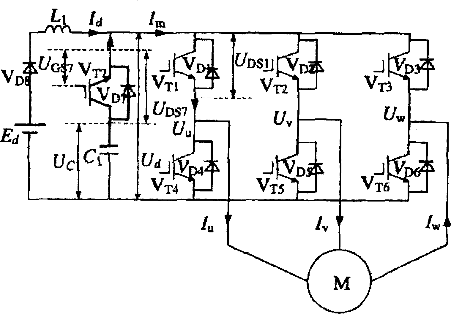
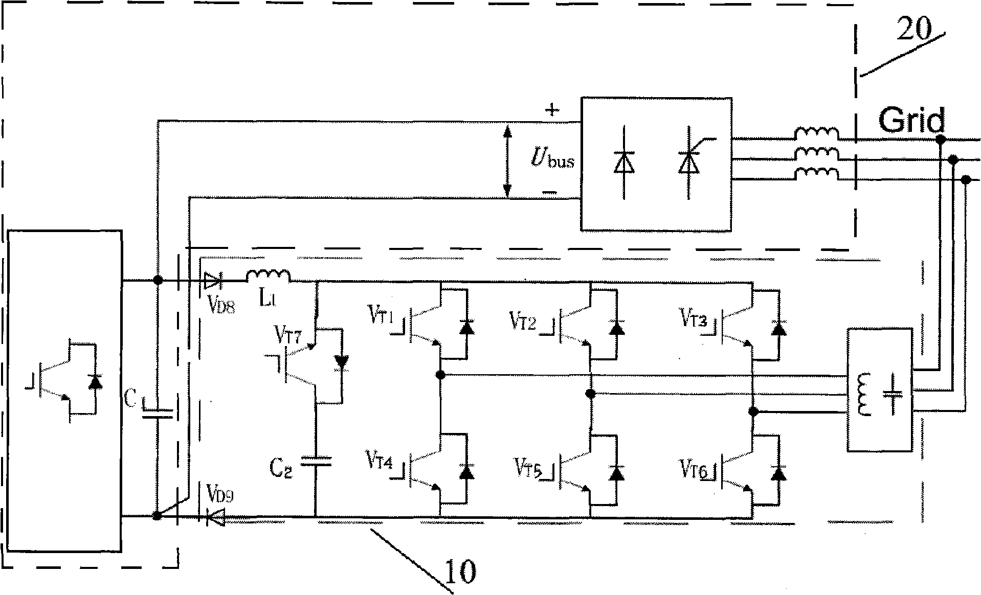
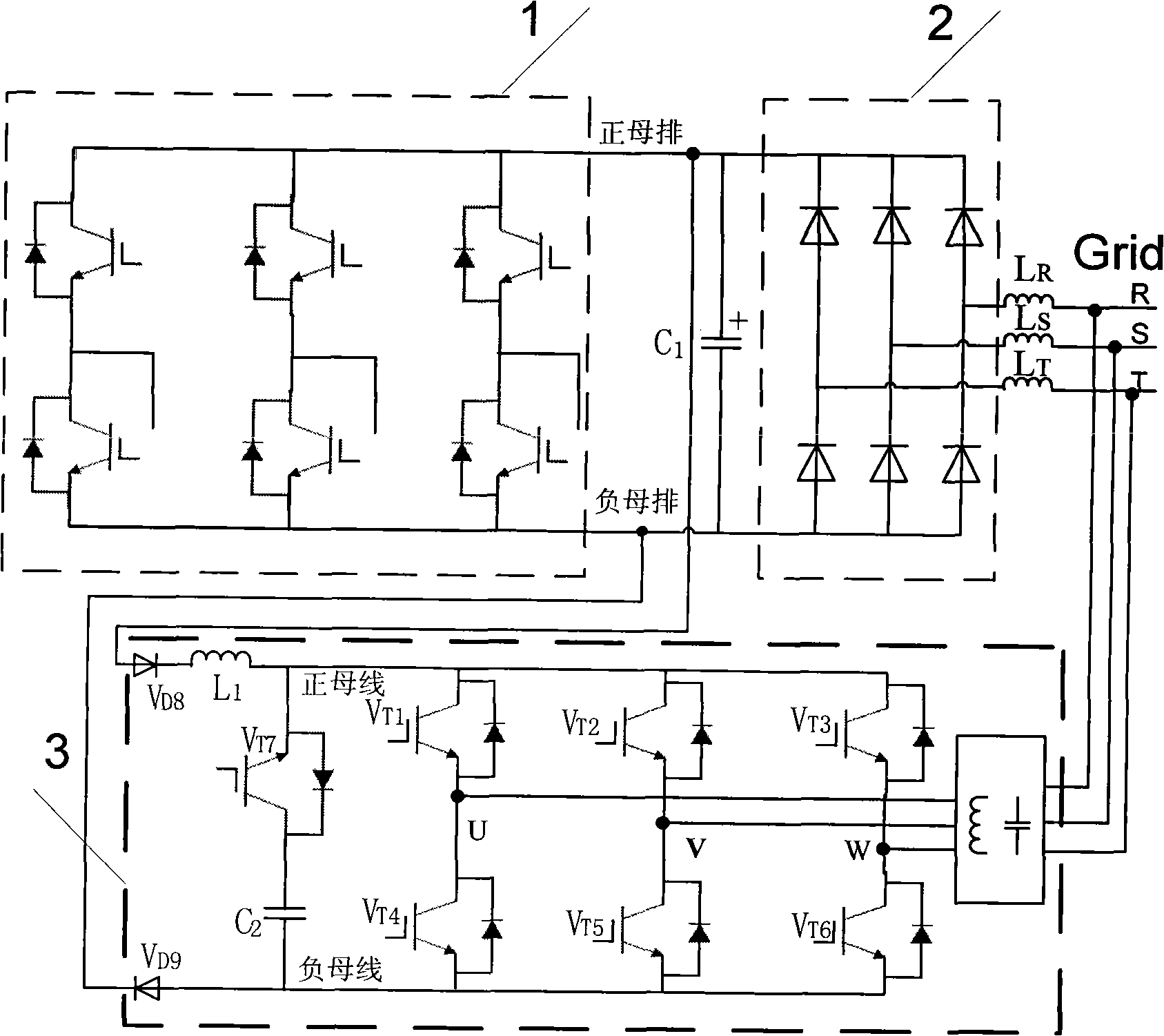
[0027] see figure 2, the energy recovery device of the present invention, it comprises frequency converter 20, two-level three-phase inverter 10 and three-phase power grid, is provided with inductance on a circuit of one end of described two-level three-phase inverter 10, and described inductance One end of the inductance is connected to the first diode VD8, the other end of the inductor is connected to the positive bus of the two-level three-phase inverter, and the current input end of the first diode VD8 is connected to the straight line of the inverter 20 On the current busbar, the current output end of the first diode VD8 is connected to the inductor; the other circuit at one end of the two-level three-phase inverter 10 is connected to the ...


PUM


Abstract

The invention discloses an energy recovery device. The device comprises a frequency converter, an inverter and a three-phase power network. An inductor is arranged on a circuit at one end of the inverter, one end of the inductor is connected with a first diode, and the other end of the inductor is connected to a three-phase bridge-arm connected positive bus of the inverter; a current input terminal of the first diode is connected to a positive DC bus bar of the frequency converter, a current output terminal of the first diode is connected with the inductor; another circuit at one end of the inverter is connected with a second diode which has opposite current direction to the first diode, a current input terminal of the second diode is connected to a three-phase bridge-arm connected negative bus of the inverter, a current output terminal of the second diode is connected to a negative DC bus bar of the frequency converter, and the other end of the inverter is connected with the three-phase power network. The device is mainly used for frequency converters in need of regenerative electric power, and realizes harmonic wave control, reactive compensation and energy feedback power network control so as to achieve energy saving effect.

Description

Technical field: [0001] The invention relates to an energy recovery device, in particular to an energy recovery device used in a frequency converter that requires regenerative power generation. Background technique: [0002] As the core industry of modern logistics, the container transportation industry is developing rapidly with each passing day. Among them, refrigerated container storage and transportation is a kind of high-profit and high-risk container storage and transportation. It needs reliable support of high technology in order to effectively avoid high risks and obtain high profits. profit. At present, the power in conventional refrigerated container thermal performance tests is generally controlled by a relay, which directly adjusts the voltage of the heater in the container, including the voltage of the heater fan. This control and adjustment method makes the power fluctuation of the system difficult to stabilize. The obtained test results It cannot meet the req...

Claims


Application Information

Patent Timeline
Patent Type & Authority Applications(China)
IPC IPC(8): H02J3/38
Inventor 吴卫民
Owner SHANGHAI MARITIME UNIVERSITY
Why Eureka
Try Eureka