

Brake caliper for disk brake
A technology of disc brakes and chucks, applied in the direction of brake components, brake types, brake actuators, etc., can solve problems such as uneven wear of brake pads 10, and achieve the purpose of avoiding quality and/or cost increases and eliminating brake pads. The effect of dynamic howling and excellent braking force
- Summary
- Abstract
- Description
- Claims
- Application Information
AI Technical Summary
Problems solved by technology
Method used
Image

Examples
no. 1 example
[0117] Here, based on figure 1 with 2 Explanation According to the first embodiment of the present invention, where reference numerals are shared in the present invention and the conventional technology, the same reference numerals are used for Figures 13 to 15 Those parts in the same as conventional technology.
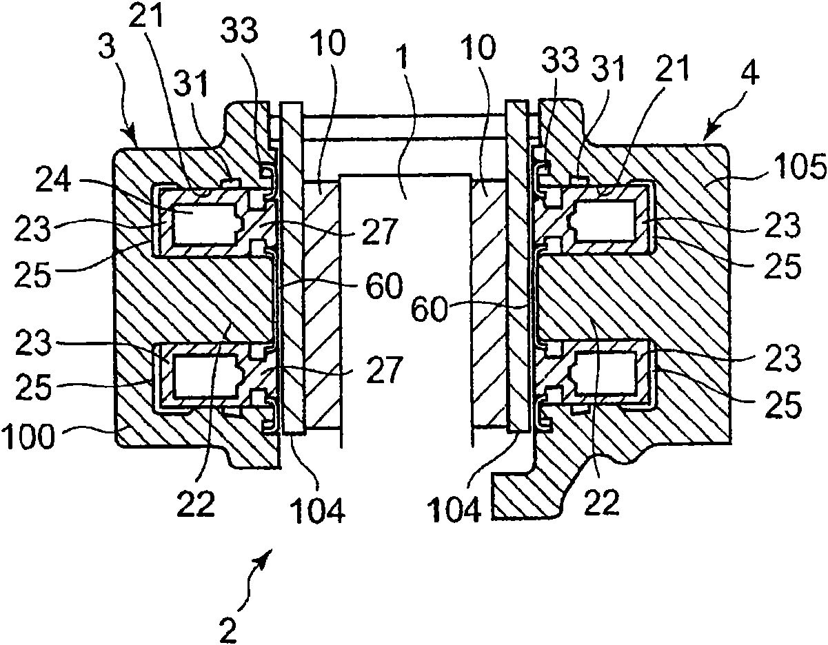
[0118] figure 1 with 2 The overall structure of the brake chuck 2 in Figures 13 to 15 The assembly structure of the brake chuck 2 in is basically the same. The brake chuck 2 is configured to clamp the disc rotor 1 with the outer part 3 and the inner part 4; .
[0119] Such as figure 1 As shown, the outer part 3 includes: an outer chuck main body 100; a hole 21 for placing a piston (brake piston) 23 so that the piston 23 can be guided in the hole 21 and slide along the axis of the hole 21; thus, A hydraulic chamber 25 is defined (provided) between the bottom wall of the hole 21 and the top (top) wall of the piston 23 so that hydraulic oil (brake fluid) pres...
no. 2 example
[0137] Here, based on Figures 3 to 6 A second embodiment of the present invention is explained.
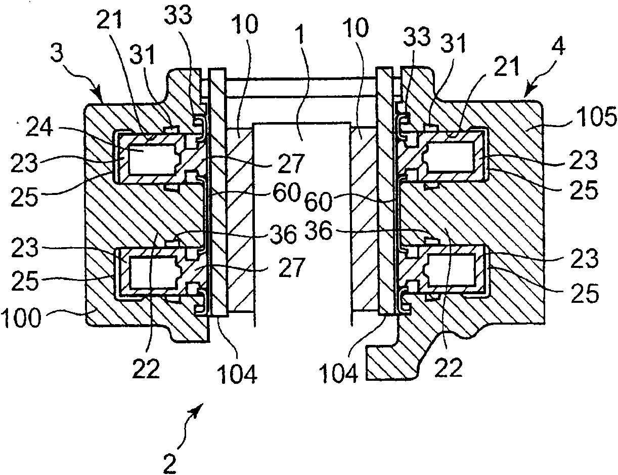
[0138] In the first embodiment, the square seal 31 is provided as an outer seal (piston outer seal) between the outer diameter peripheral wall of the hole 21 and the outer peripheral wall of the piston 23, however, in the second embodiment, A square seal 36 is additionally provided as an inner seal between the outer diameter peripheral walls of the bore 21 (piston inner seal).
[0139] From a functional point of view, by providing a groove for the square seal 36 on the side of the piston 23, the square seal 36 is not arranged on the side of the central protrusion 22 but on the side of the piston 23, there is no questionable.
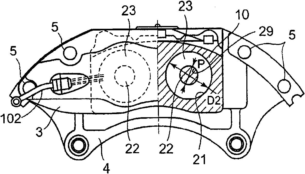
[0140] like image 3 As shown, the piston 23 contacts the quad seal 31 on the outer peripheral wall of the piston 23 and contacts the quad seal 36 on the inner peripheral wall of the piston 23 . Figure 4 It is shown by way of example how the square sea...
no. 3 example
[0149] Here, based on Figure 7 A third embodiment of the present invention is explained. This embodiment involves determining and designing the clearance between the piston 23 and the hole 21 in which the piston 23 is seated.
[0150] Figure 7 The arrangement of the piston 23 and the hole 21 is shown in detail; 1 and take the gap δ between the piston 23 and the center protrusion 22 2 placed in the hole 21; in this embodiment, it can basically be considered that the gap δ 1 not equal to gap δ 2 . In other words, different clearances are applied to the outer and inner clearances of the ring-shaped piston in order to design the brake chuck 2 .
[0151] like Figure 7 As shown, when brake fluid pressure is applied in the hydraulic chamber 25 of the chuck main body 100 or 105 , the piston 23 strongly presses the disc rotor 1 via the brake pad 10 .
[0152] On the other hand, since the disk rotor is perpendicular to the Figure 7 direction of the paper, so the brake pads ...
PUM
 Abstract
Description
Claims
Application Information