
Method for checking, correcting and compensating matching relationship of glued joint face between parts

A technology of matching relationship and surface matching, applied in metal processing equipment and other directions, can solve the problems of uneven surface of non-mold surface, skin collapse, debonding of internal glued surface, etc., so as to avoid surface unevenness and improve the matching situation. , Guarantee the effect of bonding quality

Inactive Publication Date: 2009-09-16
CHENGDU AIRCRAFT INDUSTRY GROUP
View PDF0 Cites 15 Cited by
  • Summary
  • Abstract
  • Description
  • Claims
  • Application Information

AI Technical Summary

Problems solved by technology

[0003] The purpose of the present invention is to solve the problem of bad fit between parts when bonding metal or composite parts by bag pressure, to provide a method for checking the fit relationship of the bonding surfaces between parts, and to make corrections and compensations to ensure or improve the bonding Method for the surface quality and internal bonding quality of the non-mold surface of the part
In order to solve the problems of uneven non-mold surface surface, skin collapse and internal adhesive surface debonding in the bonding of metal or composite parts,

Method used


Image

  • Method for checking, correcting and compensating matching relationship of glued joint face between parts
  • Method for checking, correcting and compensating matching relationship of glued joint face between parts

Examples


Embodiment Construction

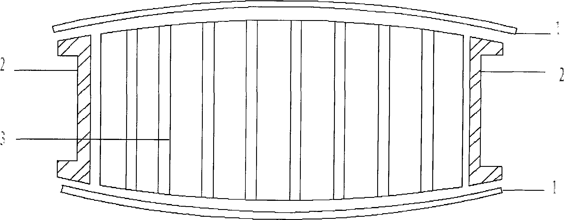
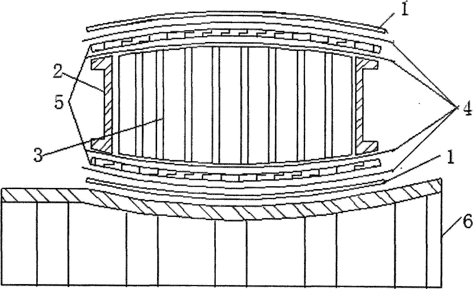
[0010] refer to figure 1 , figure 2 . According to the present invention, before bonding, the figure 1 The skin 1 shown is placed in figure 2 On the glued mold 6 shown, lay it on top of the skin 1 in sequence figure 2 Release film 4 (optional), pressure sensitive plastic 5, release film 4 (optional) as shown, then assemble and position figure 1 The skeleton part 2 and the sandwich material 3 in the figure 2 Release film 4 (optional), pressure sensitive plastic 5, release film 4 (optional) in, and finally position figure 1 Composite skin 1 and skeleton part 2 are shown. Then make a vacuum bag. Enter the tank, and simulate the pressure of bonding at a low temperature of 70°C-100°C. After leaving the tank, the deformation of the pressure-sensitive plastics is used to truly check the fit relationship between the adhesive surfaces between the parts, whether it is suitable, or interferes, or the gap is out of tolerance. Even by measuring the thickness of the pressure-se...


PUM


Abstract

The invention provides a method for checking, correcting and compensating a matching relationship of a glued joint face between parts when a metal or a composite material component is subjected to bag-pressure glued joint, the method solves defect and problem that the surface of a non-gluing mould surface is uneven, the coating is subsided and the inner glued joint face is debonded when the metal and the composite material component are subjected to the glued joint. The inventive technical proposal comprises the steps of: at first, laying sequentially isolating thin films and pressure-sensitive plastics between the coating and a sandwich material and between the glued joint faces of the skeleton parts, and positioning the isolating thin films and the pressure-sensitive plastics, laying an auxiliary material of a vacuum-bag, then manufacturing the vacuum bag, simulating the pressure of the glued joint and pressing within a tank at low temperature; when the isolating thin films and pressure-sensitive plastics are out of the tank, checking the matching relationship between the parts, measuring deforming thickness of the pressure-sensitive plastics, and by means of the deformation of the pressure-sensitive plastics, checking the matching relationship of the glued joint face between parts in a quantized manner, and afterwards, in accordance with the quantized result of the proper, interferential or spaced matching relationship, correcting and compensating the matching situation, which causes the defects of the uneven surface of the non-gluing mould surface, the subsided coating and the debonded inner glued joint face in the glued joint parts, of the glued joint face between parts.

Description

technical field [0001] The present invention relates to the method of coordinating between parts when bonding metal or composite material parts by bag pressure bonding. More specifically, the present invention relates to checking and correcting the bonding between parts when bonding metal or composite material parts by bag pressure bonding method of face-to-face relationship. Background technique [0002] In the known technology, composite materials, especially advanced composite material core structural parts molding methods, generally use the skeleton parts and skins to be cured separately and then bonded with the honeycomb core for the second time. Parts and honeycomb cores are pre-machined, then glued and vacuum bag-autoclaved. Its molding generally adopts a single-sided mold, the quality and shape of the molded surface are guaranteed by the mold, and the quality of the rest of the surface is guaranteed by vacuum bag pressure molding. Among them, the matching relations...

Claims


Application Information

Patent Timeline
Patent Type & Authority Applications(China)
IPC IPC(8): B21J5/00
Inventor 冷卫红
Owner CHENGDU AIRCRAFT INDUSTRY GROUP
Learn More