A peen forming method for a ribbed structure
A technology for shot peening and structural parts, applied in the field of shot peening, can solve the problems of deflection profile, instability, torsion, etc., and achieve the effect of increasing the amount of shot peening deformation and improving the fatigue life.
- Summary
- Abstract
- Description
- Claims
- Application Information
AI Technical Summary
Problems solved by technology
Method used
Image

Examples
Embodiment 1
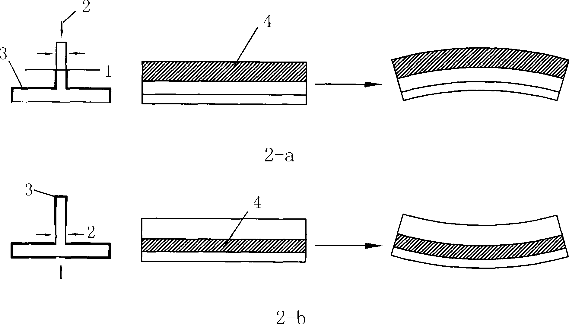
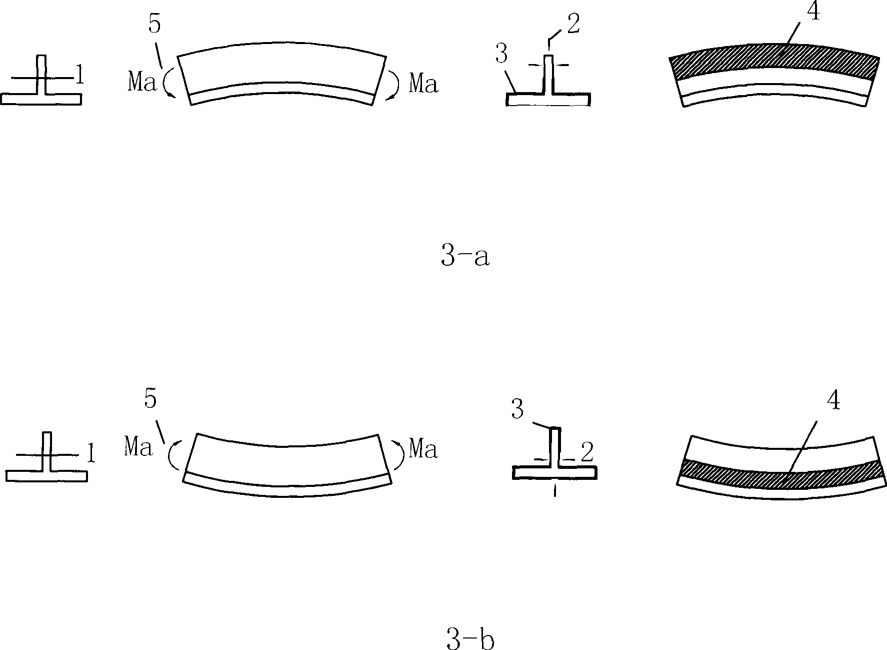
[0025] The ribbed structural parts are formed by shot blasting to form convex bending deformation along the direction of the ribs. The material is aluminum alloy 2024T351, the target curvature radius is 2500mm, the height of the ribs is 50mm, the thickness of the wall plate is 10mm, the thickness of the ribs is 6mm, and the width of the wall plate is 90mm The material shot peening method is as follows:
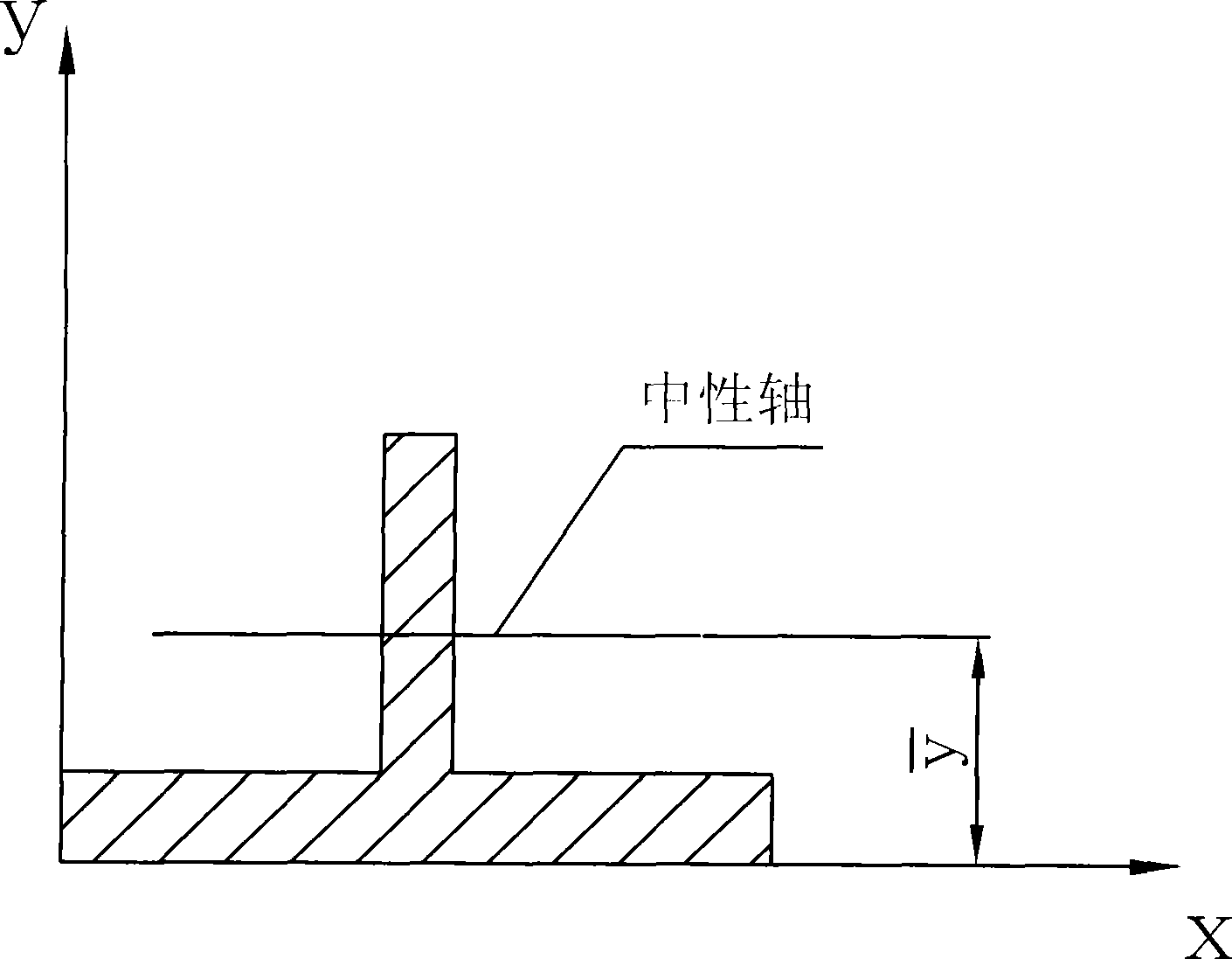
[0026] 1) Determine the position of the neutral axis, divide the cross-section of the ribbed structural member into i figures, and use the centroid coordinate formula for calculating the cross-section figures in mechanics of materials y - = Σ A i y ‾ i Σ A i Determine the neutral...
Embodiment 2
[0029] Shot-peening formed ribbed structural parts to form concave bending deformation along the direction of the ribs. The material is aluminum alloy 2024T351, the target curvature radius is 4000mm, the height of the ribs is 56mm, the thickness of the wall plate is 4mm, the thickness of the ribs is 4mm, and the width of the wall plate is 70mm The forming method is as follows:
[0030] 1) Determine the neutral axis position, y - = Σ A i y ‾ i Σ A i = 70 × 4 × 2 + 56 × 4 × 32 ...
Embodiment 3
[0033] Shot-peening formed the ribbed structural part to form a convex bending deformation along the direction of the rib, and the overall shape of the ribbed structural part is " "The material is aluminum alloy 2024T351, the target radius of curvature is 2000mm, the rib height is 45mm, the wall thickness is 9mm, the rib thickness is 8mm, the rib top width is 20mm, the rib top thickness is 6mm, and the wall panel width is 85mm. , the forming method is as follows:
[0034] 1) Determine the position of the neutral axis, divide the cross-section of the ribbed structural member into i figures, and use the centroid coordinate formula for calculating the cross-section figures in mechanics of materials y - = Σ A i y ‾ i Σ A ...
PUM
 Abstract
Description
Claims
Application Information
 - Generate Ideas
- Intellectual Property
- Life Sciences
- Materials
- Tech Scout
- Unparalleled Data Quality
- Higher Quality Content
- 60% Fewer Hallucinations
Browse by: Latest US Patents, China's latest patents, Technical Efficacy Thesaurus, Application Domain, Technology Topic, Popular Technical Reports.
© 2025 PatSnap. All rights reserved.Legal|Privacy policy|Modern Slavery Act Transparency Statement|Sitemap|About US| Contact US: help@patsnap.com