
Method for generating power by high efficient floating type wave energy by rubbing

A wave energy, floating technology, applied in ocean energy power generation, engine components, machines/engines, etc., can solve the problem that wave energy power generation technology cannot efficiently collect and convert wave energy in a large area, and achieve good power generation effect and work. Smooth, efficient capture and transition effects

Inactive Publication Date: 2009-09-16
刘威廉 +1
View PDF0 Cites 20 Cited by
  • Summary
  • Abstract
  • Description
  • Claims
  • Application Information

AI Technical Summary

Problems solved by technology

[0003] The invention provides a kneading and high-efficiency floating wave energy generation method, which solves the problem that the current wave energy generation technology cannot efficiently collect and convert wave energy in a large area

Method used


Image

  • Method for generating power by high efficient floating type wave energy by rubbing
  • Method for generating power by high efficient floating type wave energy by rubbing

Examples


specific Embodiment approach 1

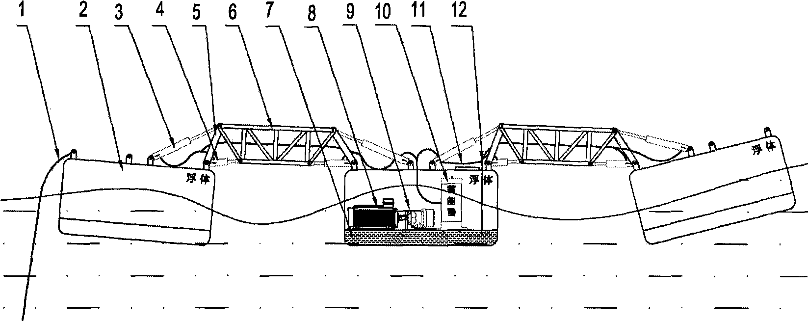
[0026] Such as figure 2 As shown, all devices are safely and organically connected together, and the whole device floats on the sea. In this specific embodiment, the mooring cable system 1 flexibly positions the entire device in the working sea area, and the floating body 2 is subjected to the fluctuation of wave energy, forcing it to form a relatively flexible swing with the kneading support frame 5 and the truss 6, forcing the hinge The distance between the hinge points at both ends of the connected upper rod pump 3 and lower rod pump 4 changes, so that the liquid inside the upper rod pump 3 and lower rod pump 4 is under strong pressure, and the high-pressure liquid is sent to the hydraulic system through the high-pressure oil pipe 11 for energy storage The pressure leveling process is carried out in the device 10, and then the liquid with stable pressure is sent into the hydraulic motor 9 to drive the rotation, thereby driving the generator 8 to rotate and generate electri...

specific Embodiment approach 2

[0027] The anchor cable system and the first floating body can be removed, the truss 6 can be directly installed on the shore platform, and the installation of other components remains unchanged.

specific Embodiment approach 3

[0028] The structures described in Embodiment 1 can also be arranged in a criss-cross pattern on the sea surface according to the requirements of power generation, and dozens or even tens of thousands of them can be installed to achieve an ideal power generation effect.


PUM


Abstract

The invention discloses a method for generating power by high efficient floating type wave energy by rubbing. A device adopting the method comprises an anchor cable system, a floating body, an upper rod pump, a lower rod pump, a rubbing support frame, a truss, a hydraulic reservoir, a generator, a hydraulic motor, a hydraulic system accumulator, a high-pressure oil tube and an oil return tube. The anchor cable system flexibly positions the whole device to float in the working sea area; the floating body is forced to sway relative to the rubbing support frame and the truss due to wave action so that the distance between the hinge points of both ends of the upper rod pump and the lower rod pump connected by a hinge of the floating body changes, thus promoting the upper rod pump and the lower rod pump to work. High pressure liquid from the two rod pumps enters the hydraulic system accumulator via the high-pressure oil tube for energy storage and pressure regulation, and then enters the hydraulic motor to drive the generator to rotate so as to generate power.

Description

technical field [0001] The invention relates to a renewable energy power generation device, in particular to a wave energy power generation system, in particular to a kneading and high-efficiency floating wave energy power generation method. Background technique [0002] Existing floating wave power generation devices are divided into two types: one is to use the changes of wave crests and troughs to turn air into high-speed flowing gas, and then the gas drives the air turbine to work. Such as Japan's "Haiming" power generation ship, "Giant Whale" and so on. However, practice has proved that the energy conversion utilization rate of this method is very low, and it has gradually withdrawn from the industry stage. The other is to use the up and down wave force of the wave to push the floating body floating on the water surface to collect wave energy, and use the energy conversion system to drive the generator to work. Such as the "Pelamis-750" equipment in the UK, this type ...

Claims


Application Information

Patent Timeline
IPC IPC(8): F03B13/22
CPCY02E10/38Y02E10/30
Inventor 刘威廉
Owner 刘威廉
Learn More