Fuel container and solid fuel

A solid fuel and fuel container technology, applied in the direction of solid fuel, fuel, solid heating fuel, etc., can solve the problems of odor emission, heat absorption effect reduction, inability to peel off, etc., and achieve the effect of suppressing a sharp temperature rise

Inactive Publication Date: 2014-02-05
NIITAKA
View PDF5 Cites 0 Cited by
  • Summary
  • Abstract
  • Description
  • Claims
  • Application Information

AI Technical Summary

Problems solved by technology

[0004] However, when a relatively large solid fuel is used or multiple solid fuels are used at one time to increase firepower, the soap component in the solid fuel burns to generate smoke and ash, which may contaminate the pot or emit a bad smell to the surroundings
[0005] From the initial stage of combustion to the middle stage of combustion of fuel such as methanol contained in solid fuel, the heat absorbed by the vaporization heat of fuel such as methanol suppresses the temperature rise of the solid fuel itself and the vicinity of the solid fuel, so combustion of soap components rarely occurs However, at the end of combustion when fuels such as methanol are burnt out, the effect of absorbing heat due to the vaporization heat of fuels such as methanol decreases, and the temperature near the solid fuel rises. Contaminates the pot, sometimes emitting an odor to the surroundings
Furthermore, the burnt soap component adheres to the fuel container containing the solid fuel, and sometimes cannot be peeled off.

Method used


Image

  • Fuel container and solid fuel
  • Fuel container and solid fuel
  • Fuel container and solid fuel

Examples


Embodiment approach 1

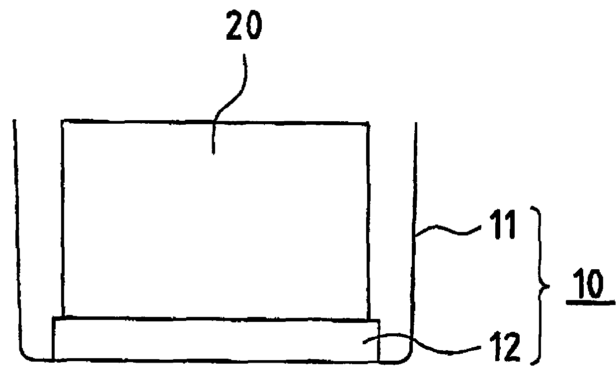
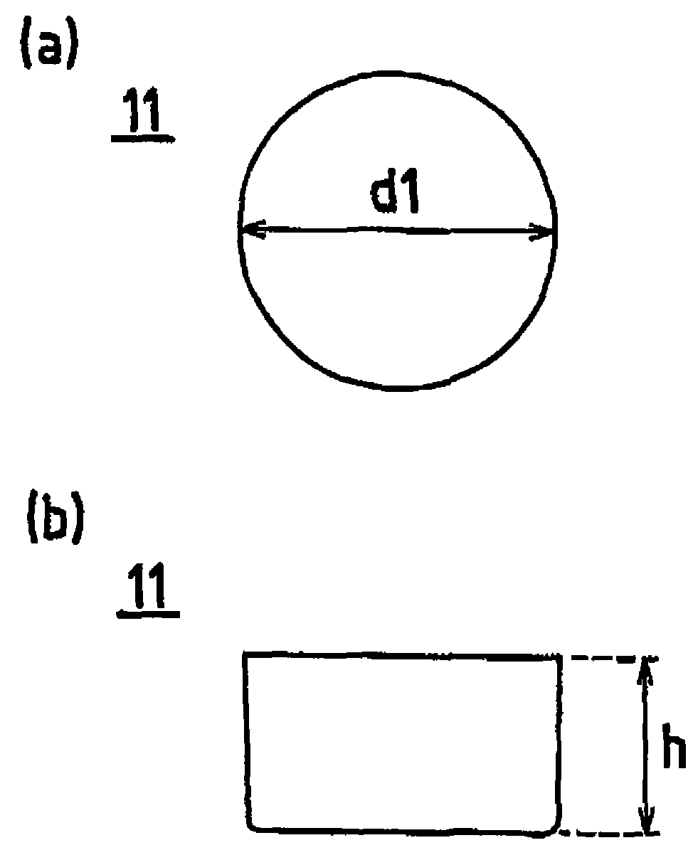
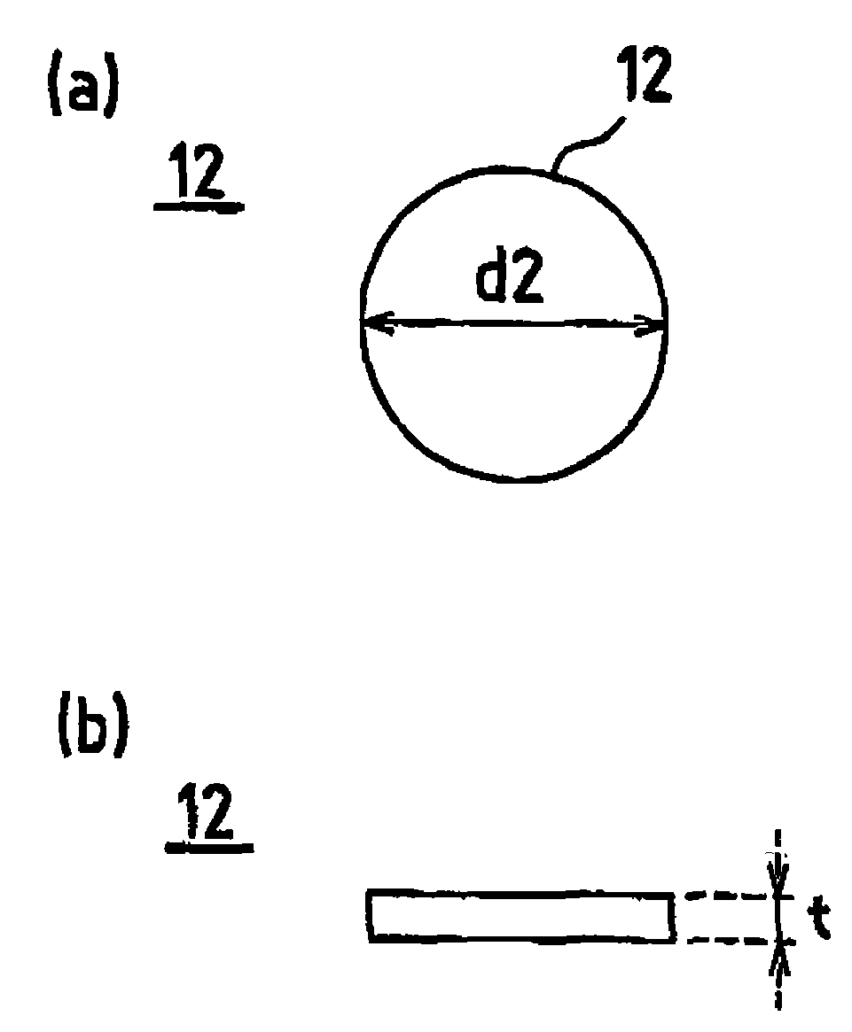
[0036] figure 1 It is a perspective side view showing a schematic configuration of a fuel container according to Embodiment 1 of the present invention. also, figure 2 yes figure 1 (a) bottom view and (b) side view of the container body of the fuel container shown in image 3 yes figure 1 (a) bottom view and (b) side view of the heat absorber of the fuel container shown in . also, Figure 4 yes figure 1 A perspective side view of a usage example of the fuel container shown in .

[0037] The fuel container 10 according to Embodiment 1 of the present invention includes a container body 11 that accommodates the solid fuel 20 and a heat absorber 12 that absorbs heat generated at the end of combustion of the solid fuel 20 .

[0038] The container main body 11 is formed in the shape of a container with an upper opening capable of accommodating the solid fuel 20 , specifically, in a cylindrical shape with a bottom.

[0039] The heat absorber 12 is formed in a disc shape on wh...

Embodiment 1~6、 comparative example 1

[0049] The fuel container 10 according to the present embodiment was placed on the center bottom of the small furnace 40, and a pot 50 filled with 1000 g of water was mounted on the upper part of the opening of the small furnace 40, and a combustion test of the solid fuel 20 was carried out. In addition, the combustion test is carried out as follows. A thermocouple is installed between the solid fuel 20 and the heat absorbing body 12, and the maximum attained temperature of this part is measured, that is, the maximum attained temperature between the ignition of the solid fuel 20 and the natural extinguishment is measured. temperature. In addition, the state of smoke generation during combustion and after extinguishment, and the state of the soap component (solid fuel 20 ) after extinguishment were evaluated.

[0050] As the pot 50, a stainless steel pot with a diameter of 175 mm and a height of 85 mm was used. In addition, as the solid fuel 20, a cylindrical solid fuel 20 hav...

Embodiment approach 2

[0075] Figure 5 It is a perspective side view showing a schematic configuration of a fuel container according to Embodiment 2 of the present invention.

[0076] The fuel container 10 according to Embodiment 2 of the present invention has almost the same structure as the fuel container 10 according to Embodiment 1, and includes a container body 11 for accommodating the solid fuel 20 and a heat absorber for absorbing heat generated at the end of combustion of the solid fuel 20. Body 12. Hereinafter, points different from Embodiment 1 will be mainly described.

[0077] The container body 10 is formed in the same shape as the first embodiment in the shape of a container with an open top, specifically, in the shape of a bottomed cylinder. In addition, the size of the container main body 10 is set to the size which can accommodate the bottom part of the heat absorber 12 formed in the container shape shown below.

[0078] The heat absorber 12 is formed in the shape of a container...


PUM

PropertyMeasurementUnit
thicknessaaaaaaaaaa
diameteraaaaaaaaaa
diameteraaaaaaaaaa

Abstract

The present invention provides a fuel container, capable of restraining the temperature of a solid fuel from increasing in a combustion final stage and restraining a soap component contained in a solid component from burning, and a solid fuel. In the fuel container (10) for burning the solid fuel (20), the fuel container is provided with an absorber (12) for absorbing the heat generated in the combustion final stage of the solid fuel (20), wherein the absorber (12) is arranged on a inner side bottom of a container body (11) receiving the solid fuel (20). By means of the above structure, it is capable of absorbing the heat generated in the combustion final stage of the solid fuel (20) by the absorber (12), so as to restrain the temperature of the solid fuel in the combustion final stage and nearby the solid fuel from increasing rapidly.

Description

technical field [0001] The present invention relates to a fuel container and a solid fuel used for burning solid fuel. Background technique [0002] Conventionally, solid fuels containing fuels such as methanol in a base material composed of alkali metal salts of fatty acids such as stearic acid (hereinafter referred to as soap components) have been used as simple fuels for portable use or table use. [0003] This kind of solid fuel has been mainly used in single-use pots in recent years, and it is also gradually used in heating large pots for multiple people. Along with this, solid fuels are gradually required to have stronger firepower and long burn time. [0004] However, when a relatively large solid fuel is used or a plurality of solid fuels are used at one time to increase firepower, the soap component in the solid fuel burns to generate smoke and ash, which may pollute the pot or emit a bad smell to the surroundings. [0005] From the initial stage of combustion to ...

Claims


Application Information

Patent Timeline
Patent Type & Authority Patents(China)
IPC IPC(8): F24B1/193F24B1/199C10L7/04
Inventor 伊藤阳次
Owner NIITAKA
Why Eureka
Try Eureka