Pipe liquid filled shear bending and forming method
A technology of shearing and bending pipes, which is applied in the field of pipe bending and forming, can solve the problems of inability to process extremely small relative bending radius pipes, etc., achieve excellent overall performance, eliminate wrinkling and cross-sectional distortion, and achieve good surface quality of workpieces
- Summary
- Abstract
- Description
- Claims
- Application Information
AI Technical Summary
Problems solved by technology
Method used
Image
Examples
specific Embodiment approach 1
[0019] Specific implementation mode 1: The liquid-filled shearing and bending forming method for pipes described in this implementation mode is that shear deformation generates material flow to realize bending, and liquid medium is used to realize internal pressure support, and punch feeding and feeding and movable mold movement are used to achieve bending. Axial force and tangential force are realized, and the stress state when the pipe is bent is adjusted through real-time control of liquid pressure, axial force and tangential force, thereby controlling deformation behavior.
specific Embodiment approach 2
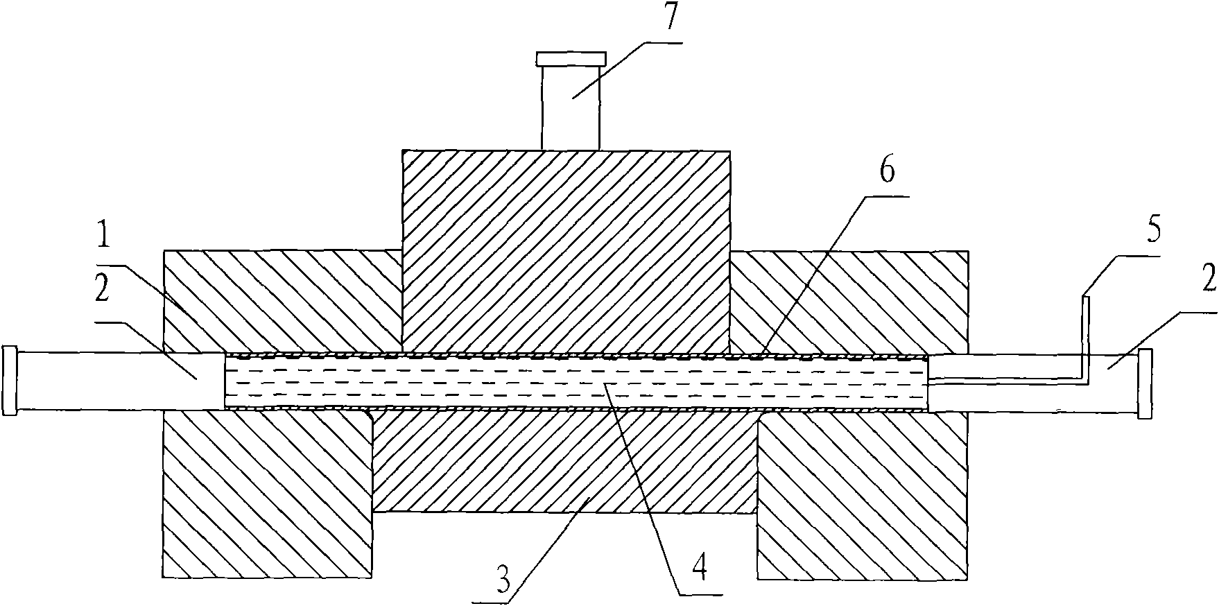
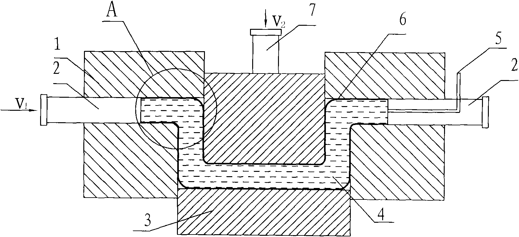
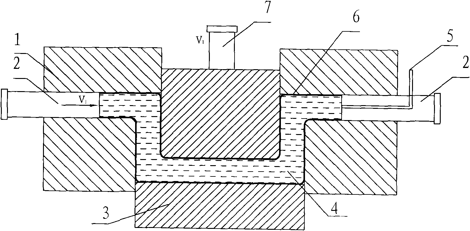
[0020] Specific implementation mode two: as Figures 1 to 6 As shown, the pipe liquid-filled shear bending forming method described in this embodiment is realized according to the following steps:
[0021] Steps, filling stage: put the tube blank 6 in the mold cavity composed of the fixed module 1 and the movable module 3, respectively install the sealing punches 2 on both ends of the tube blank 6, insert one of the sealing punches 2 Equipped with a medium input pipeline 5 communicating with the inner cavity of the tube blank 6; the tube blank 6 is filled with a liquid medium 4 through the medium input pipeline 5, and the sealing punch 2 is pushed inward to realize the sealing of the end of the tube blank 6 initial seal;
[0022] Step 2, forming stage: pressurize the liquid medium 4 in the tube blank 6 to p 1 The driving device 7 drives the movable module 3 to move in the tangential direction of the tube blank 6 relative to the fixed module 1, and at the same time, the seali...
specific Embodiment approach 3
[0025] Specific implementation mode three: as Figures 1 to 6 As shown, in this embodiment, in step 3, p 1 Between 0 ~ 1000MPa. Other steps are the same as in the second embodiment.
PUM
 Abstract
Description
Claims
Application Information
 - R&D
- Intellectual Property
- Life Sciences
- Materials
- Tech Scout
- Unparalleled Data Quality
- Higher Quality Content
- 60% Fewer Hallucinations
Browse by: Latest US Patents, China's latest patents, Technical Efficacy Thesaurus, Application Domain, Technology Topic, Popular Technical Reports.
© 2025 PatSnap. All rights reserved.Legal|Privacy policy|Modern Slavery Act Transparency Statement|Sitemap|About US| Contact US: help@patsnap.com


