Pipe liquid filled shear bending and forming method

A technology of relative bending radius and shear bending, which is applied in the field of pipe bending and forming, can solve the problems of inability to process extremely small relative bending radius pipe fittings, achieve excellent overall performance, good surface quality of workpieces, and reduce wrinkling and cross-sectional distortion tendencies Effect

Active Publication Date: 2012-01-25
HARBIN INST OF TECH
View PDF0 Cites 1 Cited by
  • Summary
  • Abstract
  • Description
  • Claims
  • Application Information

AI Technical Summary

Problems solved by technology

[0010] In order to solve the problem that the existing bending technology cannot process extremely small relative bending radius pipe fittings, the present invention further provides a method that can realize relative bending radius R b ≤0.5 pipe liquid-filled shear bending forming method

Method used


Image

  • Pipe liquid filled shear bending and forming method
  • Pipe liquid filled shear bending and forming method
  • Pipe liquid filled shear bending and forming method

Examples


specific Embodiment approach 1

[0019] Specific implementation mode 1: The liquid-filled shearing and bending forming method for pipes described in this implementation mode is that shearing deformation generates material flow to realize bending, using liquid medium to realize internal pressure support, and adopting punch feeding and refilling and the movement of movable molds to achieve bending. Axial force and tangential force are realized, and the stress state when the pipe is bent is adjusted through real-time control of liquid pressure, axial force and tangential force, thereby controlling deformation behavior.

specific Embodiment approach 2

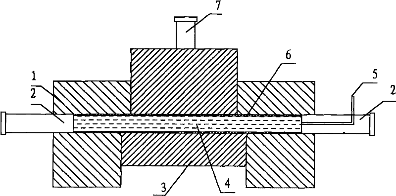
[0020] Specific implementation mode two: as Figures 1 to 6 As shown, the pipe liquid-filled shear bending forming method described in this embodiment is realized according to the following steps:

[0021] Step 1, filling stage: put the tube blank 6 in the mold cavity composed of the fixed module 1 and the movable module 3, install the sealing punches 2 on both ends of the tube blank 6, and install the sealing punch 2 on one of the sealing punches 2 A medium input pipeline 5 communicating with the inner cavity of the tube blank 6 is inserted; the liquid medium 4 is filled into the tube blank 6 through the medium input pipeline 5, and at the same time, the sealing punch 2 is pushed inward to realize the sealing of the tube blank 6 end. the initial seal;

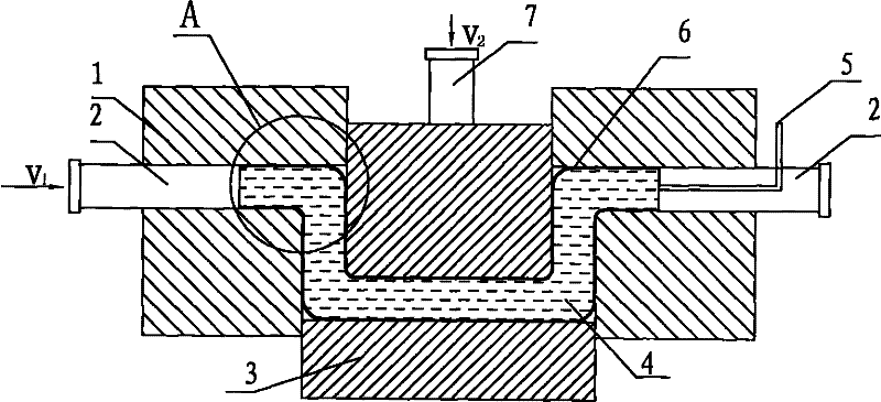
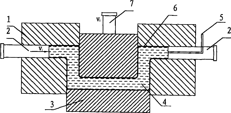
[0022] Step 2, forming stage: pressurize the liquid medium 4 in the tube blank 6 to p 1 The driving device 7 drives the movable module 3 to move tangentially along the tube blank 6 relative to the fixed module 1, and the sea...

specific Embodiment approach 3

[0025] Specific implementation mode three: as Figures 1 to 6 As shown, in this embodiment, in step 2, p 1 Between 0 ~ 1000MPa. Other steps are the same as in the second embodiment.


PUM


Abstract

A pipe liquid filled shear bending and forming method capable of realizing a relative bending dadius Rb<=0.5 relates to a pipe bending and forming method. The invention solves the problem that pipe fittings with tiny semidiameters relatively bending cannot be machined in the existing bending technology. In the method, deformation is sheared to cause material flow and realize being, internal pressure support is realized by using a liquid medium, axial force and twisting force are realized by using a plunger chip for feeding and the motion of a loose mold, and the stress condition when pipe bending is adjusted by controlling the liquid pressure, the axial force and the twisting force in real time, thereby controlling deformational behavior. The method has the concrete steps of filling stage, forming stage and shaping stage. The inventive method keeps mould cavity formed by a fixed module and a moving module always tightly attach to an outer surface of a tube blank deformation segment during the whole process from a primary state of the pipe shear bending and deformation to a deformation ending state, and then to a compression and shaping state. The pipe fittings with tiny semidiameters in which the relatively bending semidiameter Rb is less than or equal to 0.5 can be manufactured by using the method in the invention.

Description

technical field [0001] The invention relates to a pipe bending forming method. Background technique [0002] Aeronautical and aerospace components require high reliability, high safety and lightest possible weight, so strict requirements are put forward for structural integrity, structural form and occupied space. It is necessary to ensure the overall reliability of the structure and at the same time On the basis of meeting the strength requirements, the lightest possible mass is adopted, and the smallest possible space is occupied under the premise of meeting the structural requirements. [0003] Due to the limitation of structural space, the pipelines of small aero-engines and UAVs require the use of extremely small bending radius tubes, and their relative bending radius R b ≤0.5(R b is the ratio of the radius r of the neutral layer of the pipe bending to the diameter D of the pipe, Figure 4 shown), the materials used include aluminum alloys, titanium alloys and superal...

Claims


Application Information

Patent Timeline
Patent Type & Authority Patents(China)
IPC IPC(8): B21D7/06B21D7/16
CPCB21D9/15
Inventor 苑世剑韩聪
Owner HARBIN INST OF TECH
Why Eureka
Try Eureka