Method for continuously hoisting rolling mill housings by hydraulic pushing and lifting

A rolling mill archway, hydraulic lifting technology, applied in cranes, traveling mechanisms, transportation and packaging, etc., can solve the problems of insufficient crane lifting capacity, large lifting cost of hydraulic jacking and lifting, and long construction period, so as to save trouble, The lifting process is simple and the effect of improving the safety factor

Inactive Publication Date: 2009-09-23
CHINA FIRST METALLURGICAL GROUP
View PDF5 Cites 13 Cited by
  • Summary
  • Abstract
  • Description
  • Claims
  • Application Information

AI Technical Summary

Problems solved by technology

[0002] With the development of the metallurgical industry, the number and weight of archways in the same production line are increasing. Moreover, the hoisting capacity in the factory building is not enough. How to lift large-tonnage archways at the construction site and continuously hoist them in place for installation has become a problem. The existing hoisting technologies for large parts basically adopt large-scale crane hoisting, double-machine hoisting by crane, double-machine hoisting by driving, double-machine hoisting by driving and crane, and single-piece hoisting by hydraulic jacking, but all of them are subject to great influence. For example: crane hoisting is very limited by the site, driving hoisting is limited by its lifting capacity, and the cost of hydraulic jacking and hoisting of single-piece hoisting is quite large and the construction period is quite long

Method used


Image

  • Method for continuously hoisting rolling mill housings by hydraulic pushing and lifting
  • Method for continuously hoisting rolling mill housings by hydraulic pushing and lifting
  • Method for continuously hoisting rolling mill housings by hydraulic pushing and lifting

Examples


Embodiment Construction

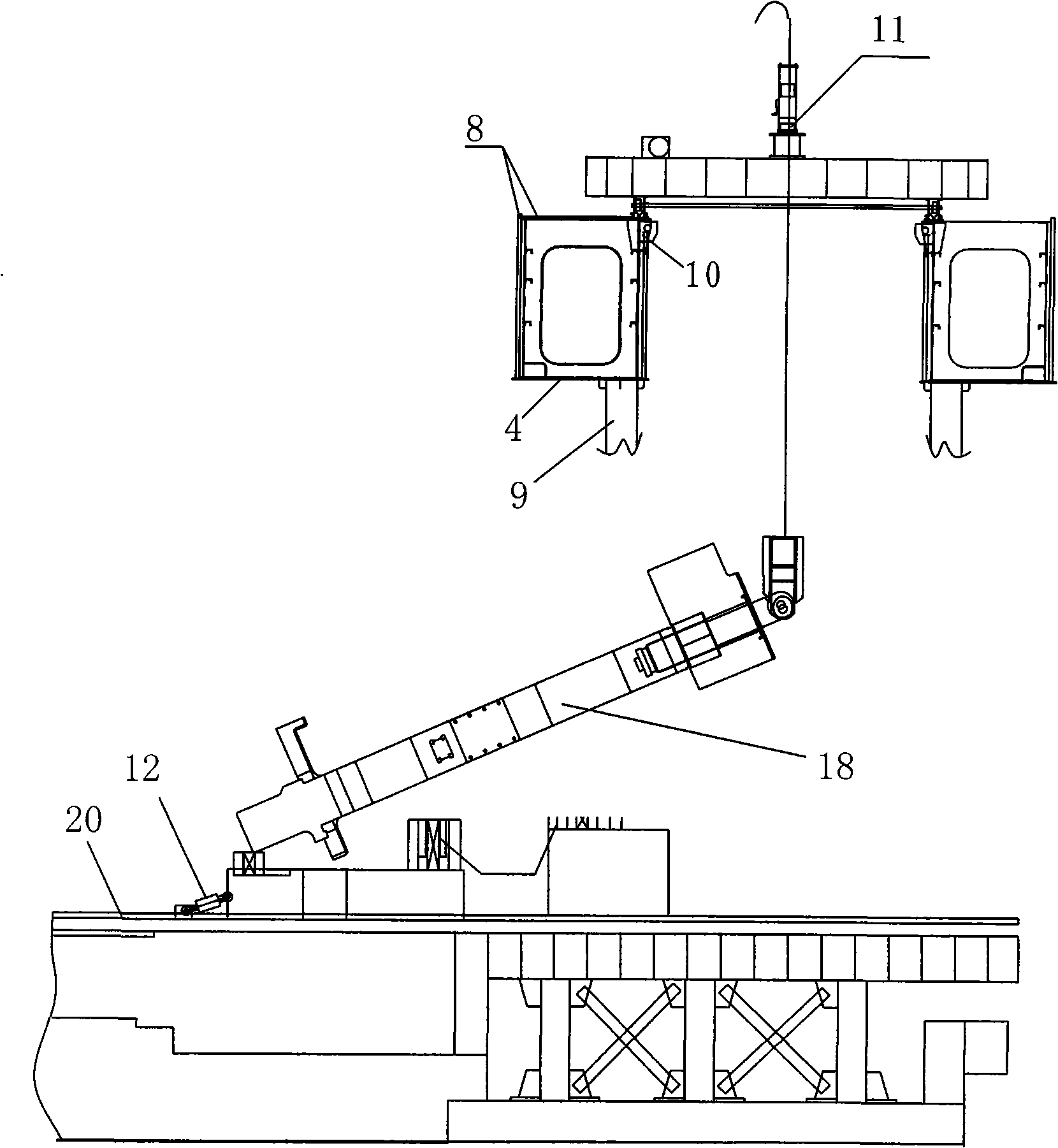
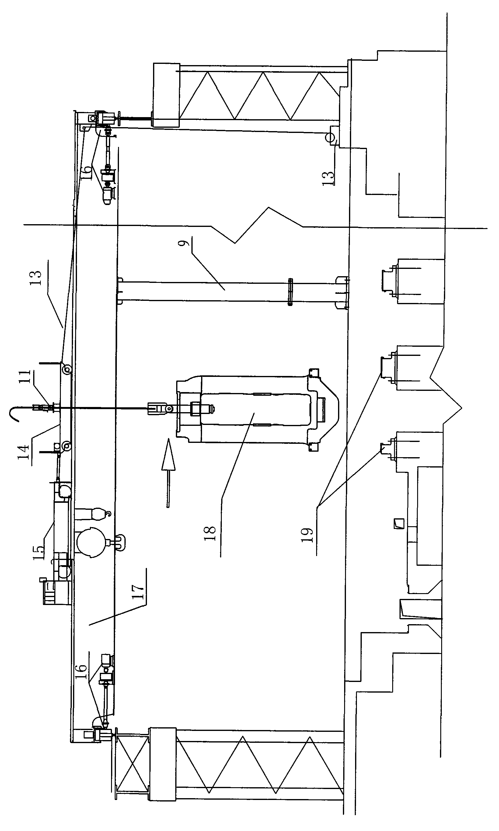
[0014] The method provided by the present invention for continuously hoisting and hoisting the rolling mill archway by means of hydraulic jacking is specifically as follows: use the crane as a platform, install a temporary trolley 14 with the same span as the trolley on the trolley, and then install the hydraulic hoist 11 on the trolley 14, and a movable support 9 is connected under the main beam of the vehicle to increase the load capacity of the main beam of the vehicle, and a set of hydraulic propeller 12 is arranged on the ground, and the archway 18 is hoisted by the hydraulic propeller 12 and the hydraulic hoist 11, and then The archway is hoisted to the installation position by driving, temporary trolley 14, hydraulic hoist 11, and winch 13, and the vertical and horizontal movements are free to realize the continuous hoisting and in-position work of multiple archways.

[0015] The specific steps of the method include:

[0016] (1) Disconnect the movable support 9 under t...


PUM


Abstract

The invention relates to a method for continuously hoisting rolling mill housings by hydraulic pushing and lifting. The method comprises the following steps: a traveling crane is taken as a platform, the traveling crane is equipped with a makeshift trolley (14) which has the same span as that of a trolley of the traveling crane, then a hydraulic lifter (11) is positioned on the makeshift trolley, a movable support (9) is connected below a main beam (17) of the traveling crane so as to increase the loading capacity of the main beam of the traveling crane, a hydraulic propeller (12) is arranged on the ground, then the mill housings (18) are lifted and hoisted to the mounting position by the traveling crane, the makeshift trolley, the hydraulic lifter and a hoister (13), and the mill housing moves freely in the vertical and horizontal directions, thus realizing continuous hoisting of a plurality of the milling housings in place. The method has the advantages of being capable of realizing the continuous hoisting of the milling housings, short construction period, simple hoisting process and easy operation, thus improving construction safety factor and lowering construction cost. The method is especially suitable for realizing the continuous hoisting of the milling housings under the condition that lifting capacity of the traveling cranes in a factory building can not meet the requirement of mounting the mill housings.

Description

technical field [0001] The invention relates to the field of crane hoisting in the metallurgical industry, in particular to a method for continuously hoisting and hoisting a rolling mill archway by using hydraulic jacking to lift the archway when the lifting capacity of the driving of the factory building cannot satisfy the installation of the archway in place. Background technique [0002] With the development of the metallurgical industry, the number and weight of archways in the same production line are increasing. Moreover, the hoisting capacity in the factory building is not enough. How to lift large-tonnage archways at the construction site and continuously hoist them in place for installation has become a problem. The existing hoisting technologies for large parts basically adopt large-scale crane hoisting, double-machine hoisting by crane, double-machine hoisting by driving, double-machine hoisting by driving and crane, and single-piece hoisting by hydraulic jacking, ...

Claims


Application Information

Patent Timeline
Patent Type & Authority Applications(China)
IPC IPC(8): B66C17/26B66C9/10
Inventor 冯纯钢尉峰蒯汉保陶红松马秉俊
Owner CHINA FIRST METALLURGICAL GROUP
Why Eureka
Try Eureka