
Electromagnetic fuel injection valve

A fuel injection valve, electromagnetic technology, applied in the direction of fuel injection devices, charging systems, machines/engines, etc., can solve the problems such as the reduction of the magnetic circuit cross-sectional area of ​​the coil shell, and the magnetic characteristics of the electromagnetic fuel injection valve are not optimal, etc. Achieve the effect of improving the magnetic properties, suppressing the cross-sectional area of ​​the magnetic circuit, and suppressing the transmission

Active Publication Date: 2012-06-20
HITACHI ASTEMO LTD
View PDF5 Cites 0 Cited by
  • Summary
  • Abstract
  • Description
  • Claims
  • Application Information

AI Technical Summary

Problems solved by technology

However, since these cutouts reduce the cross-sectional area of ​​the magnetic circuit in the coil case, it is not preferable in terms of the magnetic characteristics of the electromagnetic fuel injection valve.

Method used


Image

  • Electromagnetic fuel injection valve
  • Electromagnetic fuel injection valve
  • Electromagnetic fuel injection valve

Examples


Embodiment Construction

[0045] Hereinafter, embodiments of the present invention will be described based on preferred embodiments of the present invention shown in the drawings.

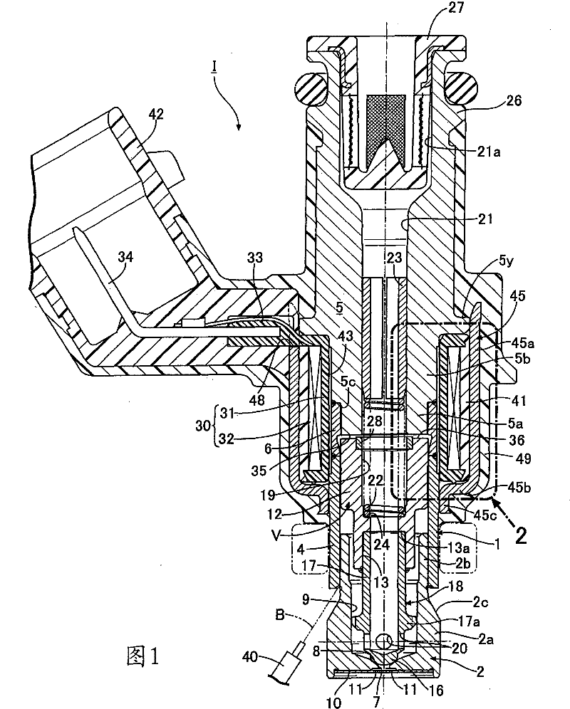
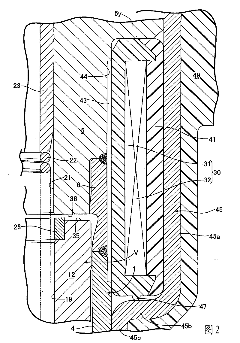
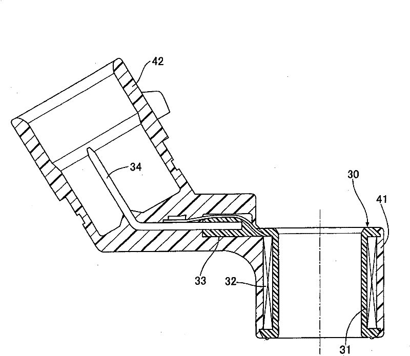
[0046] figure 1 It is a longitudinal sectional view of the electromagnetic fuel injection valve for an internal combustion engine according to the first embodiment of the present invention, figure 2 yes figure 1 2 enlargements of , image 3 is an independent longitudinal sectional view of a coil assembly with a coupling in the electromagnetic fuel injection valve, Figure 4 represents a second embodiment of the invention, is with figure 2 Corresponding sectional view.

[0047] First, start with Figure 1 ~ Figure 3 A first embodiment of the invention is shown for illustration.

[0048] existfigure 1 and figure 2 Among them, the valve sleeve 1 of the electromagnetic fuel injection valve 1 for an internal combustion engine is composed of the following parts: a cylindrical valve seat member 2; a magnetic cylinder 4 c...


PUM


Abstract

An object of the present invention is to provide an electromagnetic fuel injection valve in which the strength of a coil assembly can be enhanced while the reduction in cross-sectional area of magnetic path of a coil housing is prevented, and moreover the sound insulating properties are excellent. In an electromagnetic fuel injection valve, a first sound insulating resin layer (41) is formed at the outer periphery of a coil assembly (30), and the first sound insulating resin layer (41) and a coupler (42) are molded integrally to form the coil assembly (30) with the coupler (42); a bobbin (31)of the coil assembly (30) with the coupler (42) is fitted onto the outer peripheral surfaces of a valve housing (1) and a stationary core (5), and a sound insulating air layer (43) is formed between the fitted peripheral surfaces; a coil housing (45) for accommodating the coil assembly (30) with the coupler (42) is fitted and fixed to the valve housing (1) and the stationary core (5); and a second sound insulating resin layer (49) is formed so as to cover the outer periphery of the valve housing (1) and the outer periphery of the root of the coupler (42).

Description

technical field [0001] The present invention relates to an electromagnetic fuel injection valve mainly used in a fuel supply system of an internal combustion engine, and particularly to an improvement of an electromagnetic fuel injection valve whose valve housing has a valve at the front end. Seat, the valve sleeve contains a valve assembly, the valve assembly is composed of a valve core cooperating with the valve seat and a movable iron core connected with the valve core, a fixed iron core is connected to the rear end of the valve sleeve, When the fixed iron core is excited, it attracts the movable iron core and opens the valve core. A coil assembly is arranged on the outer circumference from the valve sleeve to the fixed iron core. The coil assembly consists of a bobbin and a coil. It is composed of a coil that is installed on the bobbin and excites the fixed iron core when energized, and a connector for holding the power supply terminal connected to the coil is arranged on ...

Claims


Application Information

Patent Timeline
Patent Type & Authority Patents(China)
IPC IPC(8): F02M51/06
CPCF02M51/005F02M51/0664F02M51/061F02M51/0682F02M51/0614
Inventor 大村知之松尾大辅佐藤和彦
Owner HITACHI ASTEMO LTD
Learn More