Gas control valve device of revolution film type fuel gas meter

A membrane gas meter and gas valve technology, which is applied to valve devices, sliding valves, valve details, etc., can solve the problems of increasing the pressure loss of the gas meter, affecting the measurement accuracy of the gas meter, and occupying the cross-sectional area of ​​the gas channel. Small cross-sectional area, low manufacturing process difficulty, and reduced pressure loss

Inactive Publication Date: 2009-09-23
荣成市宇翔实业公司
View PDF6 Cites 2 Cited by
  • Summary
  • Abstract
  • Description
  • Claims
  • Application Information

AI Technical Summary

Problems solved by technology

However, in the above schemes, the central shaft is fixedly installed in the core housing, and the transmission part (shaft sleeve or sleeve of the central eccentric gear) is inserted in the central hole of the valve cover and sleeved on the central shaft. Above, the valve cover is rotated and fitted on the valve seat, and rotates around the central axis together with the transmission part. The central axis plays the role of connecting the positioning core shell, the valve seat and the valve cover, so that the axial length of the central axis is too long , the central axis of this structure tends to be skewed in the process of fixing the core shell, which causes the valve cover to tilt, thus affecting the measurement accuracy of the gas meter, and the core shell and the valve cover must be made respectively The positioning boss of the central axis increases the difficulty of the process; at the same time, the positioning boss occupies the cross-sectional area of ​​the gas channel and increases the pressure loss of the gas meter

Method used


Image

  • Gas control valve device of revolution film type fuel gas meter

Examples


Embodiment Construction

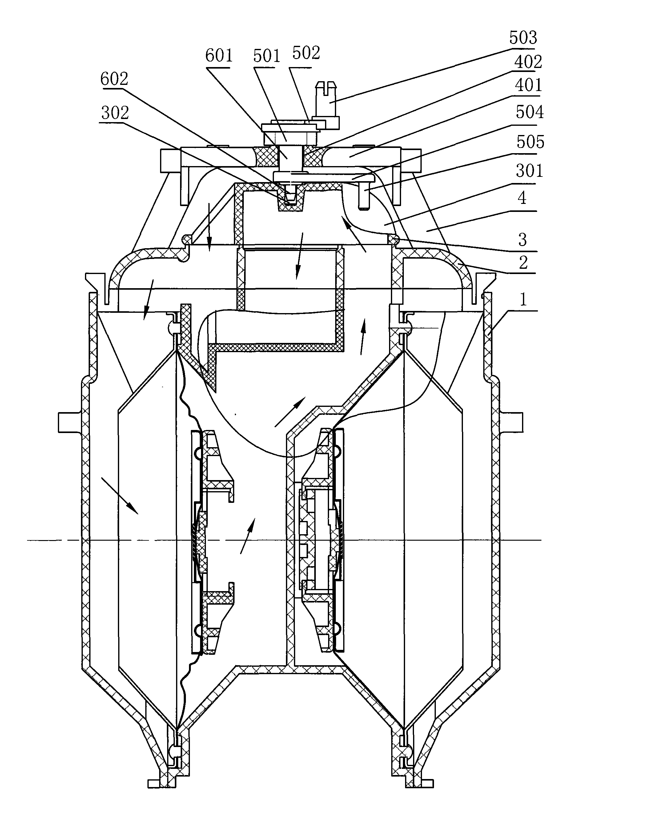
[0011] As shown in the drawings, a gas control valve device for a rotary membrane gas meter includes a valve seat 2 . The valve seat 2 is sealed and fixed on the top of the core housing 1 by a sealant.

[0012] The present invention also includes a valve cover 3 . As shown in the drawings, the valve cover 3 is rotatably fitted on the valve seat 2, and there is a flat sealing surface between the valve cover 3 and the valve seat 2. In the accompanying drawings, the upper end surface of the valve cover 2 is formed with a positioning counterbore 302 that does not penetrate the end surface of the valve cover, and a shifting groove 301 is formed on the side end surface of the valve cover 2 .

[0013] The present invention also includes a gear bracket 4 . The gear bracket 4 is fixedly assembled on the core housing 1 by fixing screws. As shown in the drawings, the upper frame body 401 of the gear bracket 1 is located above the valve cover 3 , and a positioning through hole 402 is o...


PUM


Abstract

The invention relates to a gas control valve device of a revolution film type fuel gas meter. The gas control valve device comprises a valve seat which is hermetically fixed with a core shell, a valve cover which is rotatably matched on the valve seat, a positioning piece, a transmission piece and a gear bracket which is arranged on the core shell, wherein the transmission piece consists of a transmission gear, transmission shafts which are arranged at both ends of the transmission gear and are eccentric with the transmission gear and a shifting shaft; and the shifting shaft is positioned in a shifting groove of the valve cover. The gas control valve device is characterized in that the valve cover is provided with a positioning sinkhole; an upper bracket body of the gear bracket is provided with a positioning through hole; the positioning piece consists of a first positioning shaft and a second positioning shaft between the transmission gear and the shifting shaft and sequentially coaxial with the transmission gear, wherein the first positioning shaft is matched in the positioning through hole of the gear bracket, and the lower end of the first positioning shaft is axially limited facing to the valve cover; the second positioning shaft is assembled in the positioning sinkhole of the valve cover, and the valve cover rotates around the second positioning shaft and is radially positioned by the second positioning shaft. The gas control valve device has simple structure, easy part processing and high measuring precision of the fuel gas meter.

Description

technical field [0001] The invention relates to a gate valve or slide valve with a rotary closing element and a flat sealing surface, especially a gas control valve device suitable for a rotary membrane gas meter. Background technique [0002] As we all know, the core part of the diaphragm gas meter is composed of a core housing, a diaphragm metering chamber, an air control valve device, and a connecting rod gear transmission mechanism. components. The membrane gas meter is divided into a sliding membrane gas meter and a rotary membrane gas meter according to the difference in the relative motion between the valve cover and the valve seat. The valve seat of the rotary membrane gas meter is sealed and fixed on the core body, and the valve cover is positioned on the valve seat by the positioning part, and is driven by the transmission part to make a rotary motion on the valve seat, and the diaphragm metering is continuously realized. chamber intake and exhaust. Based on the...

Claims


Application Information

Patent Timeline
IPC IPC(8): F16K3/02F16K27/04F16K27/12G01F11/08
Inventor 邹积健
Owner 荣成市宇翔实业公司
Why Eureka
Try Eureka