Method for optimizing switching process and base station equipment
A technology of base station and source base station, which is applied in the directions of access restriction, electrical components, wireless communication, etc., to improve the handover success rate, reduce the handover delay, and reduce the overhead.
- Summary
- Abstract
- Description
- Claims
- Application Information
AI Technical Summary
Problems solved by technology
Method used
Image

Examples
Embodiment 1
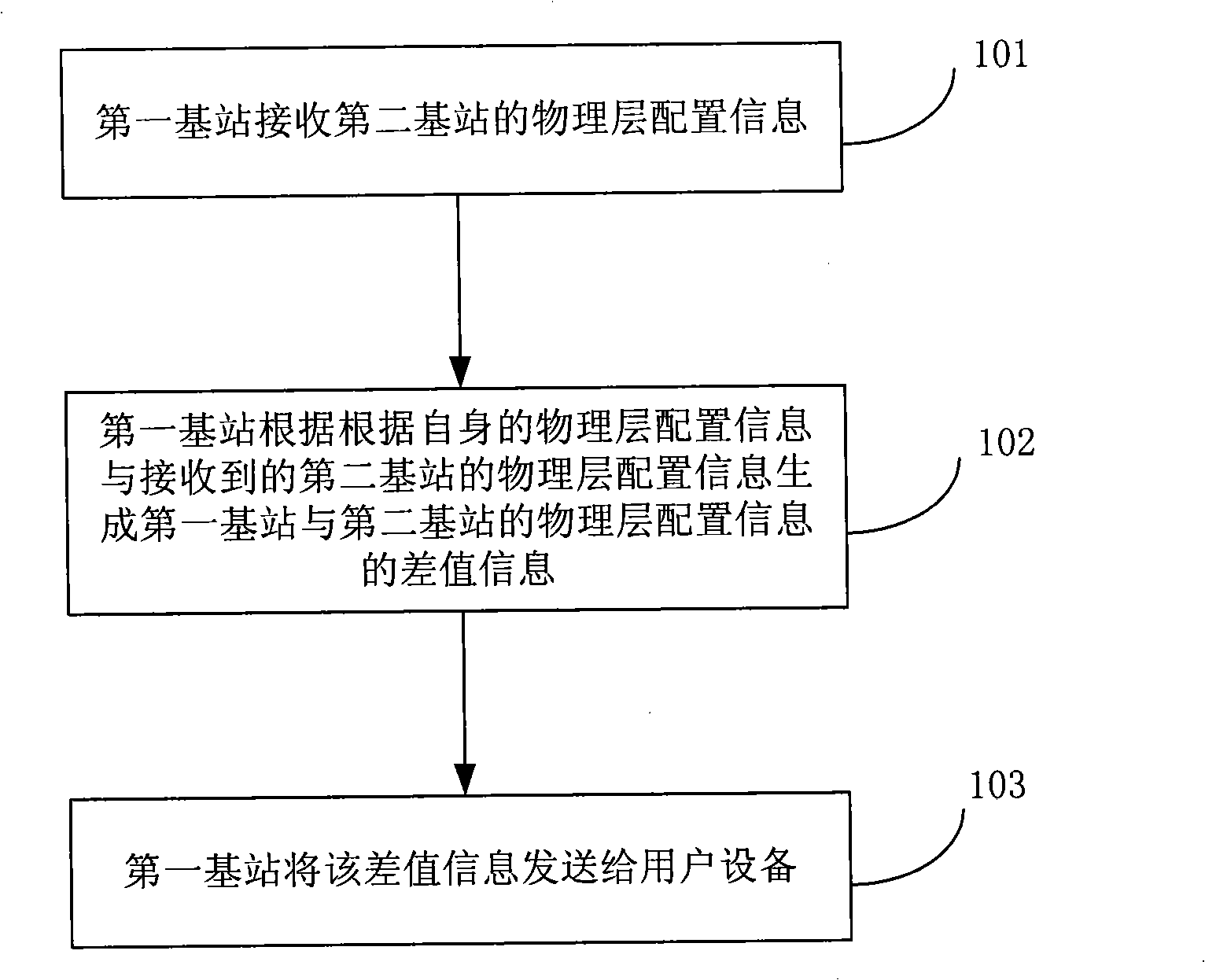
[0030] An embodiment of the present invention provides a method for optimizing handover in an LTE system. Such as figure 2 As shown, the method includes the following steps:
[0031] 101. A first base station receives physical layer configuration information of a second base station.
[0032] Wherein, the physical layer configuration information is some physical layer parameters related to the handover process. For example, downlink system bandwidth, uplink system bandwidth, RACH (Random Access Channel, random access channel) configuration of the cell, and the like. For the definitions of these parameters, reference may be made to the definitions in the prior art, which will not be repeated here.
[0033] 102. The first base station generates difference information between the physical layer configuration information of the first base station and the second base station according to its own physical layer configuration information and the received physical layer configurat...
Embodiment 2
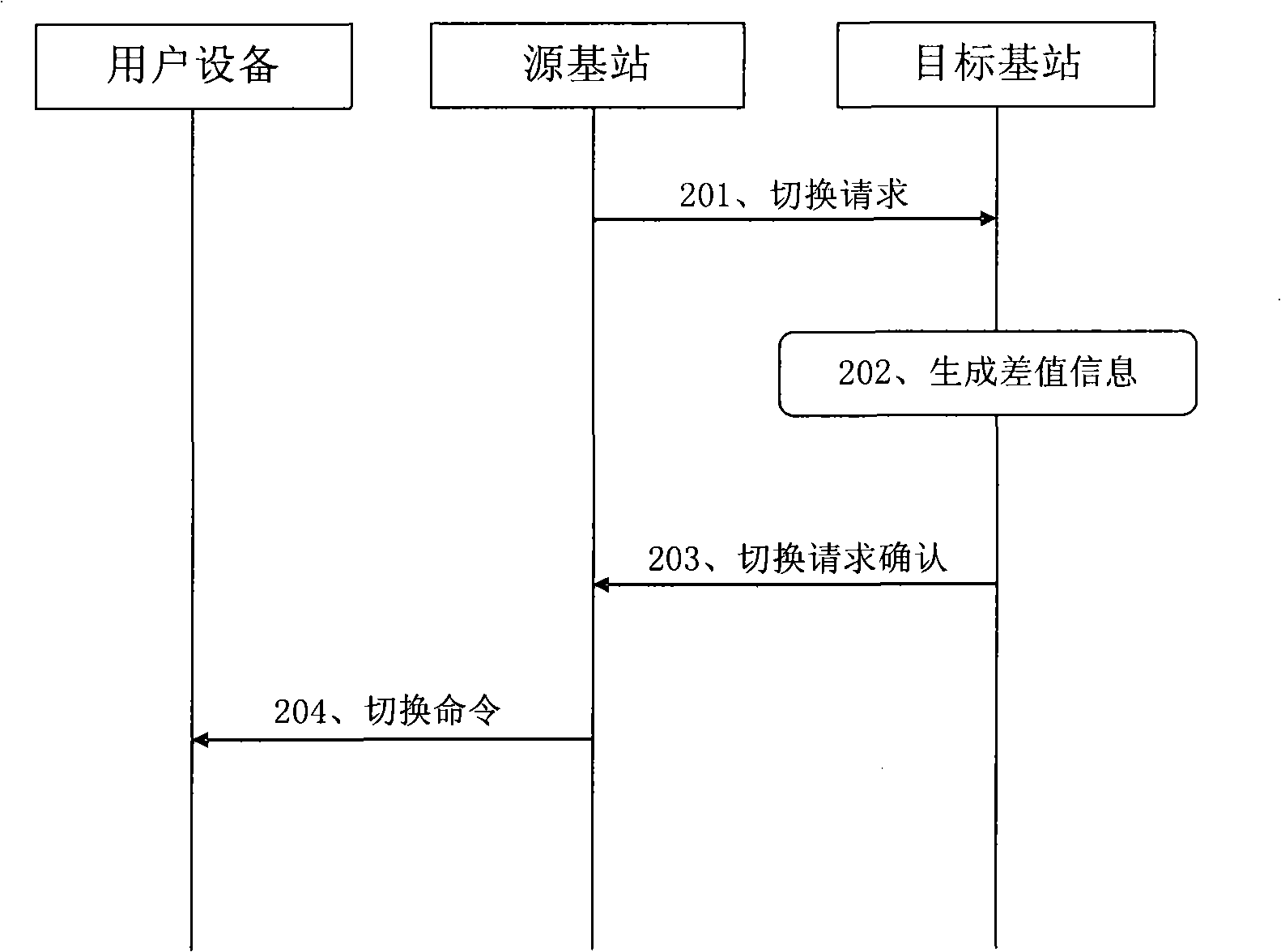
[0041] In this embodiment, taking the first handover manner as an example, a method for optimizing handover when user equipment is handed over from a source base station to a target base station is described. Such as image 3 As shown, its main processes include:
[0042] 201. The source base station sends a handover request message to the target base station. Wherein, the handover request message includes physical layer configuration information of the source base station.
[0043] 202. The target base station generates difference information between the physical layer configuration information of the source base station and the target base station.
[0044] In this step, the target base station generates difference information by comparing its own physical layer configuration information with the received physical layer configuration information of the source base station.
[0045] The difference information is the difference between the physical layer configuration infor...
Embodiment 3
[0052] In this embodiment, taking the first handover manner as an example, a method for optimizing handover when user equipment is handed over from a source base station to a target base station is described. Such as Figure 4 As shown, its main processes include:
[0053] 301. The source base station sends a handover request message to the target base station.
[0054] This step is consistent with the steps in the prior art, and the handover request message does not include the physical layer configuration information of the source base station.
[0055] 302. The target base station returns a handover request confirmation message to the source base station.
[0056] In this step, the physical layer configuration information of the target base station is included in the handover request confirmation message.
[0057] 303. The source base station generates difference information between the physical layer configuration information of the target base station and the source ba...
PUM
 Abstract
Description
Claims
Application Information
 - R&D
- Intellectual Property
- Life Sciences
- Materials
- Tech Scout
- Unparalleled Data Quality
- Higher Quality Content
- 60% Fewer Hallucinations
Browse by: Latest US Patents, China's latest patents, Technical Efficacy Thesaurus, Application Domain, Technology Topic, Popular Technical Reports.
© 2025 PatSnap. All rights reserved.Legal|Privacy policy|Modern Slavery Act Transparency Statement|Sitemap|About US| Contact US: help@patsnap.com