System and method for employing a resonant scanner in an X-Y high speed drilling system

A technology of scanners and scanning units, applied in the direction of instruments, manufacturing tools, optical components, etc., can solve the problems of adding motors, limitations, etc.

Active Publication Date: 2009-09-23
诺万达公司
View PDF4 Cites 8 Cited by
  • Summary
  • Abstract
  • Description
  • Claims
  • Application Information

AI Technical Summary

Problems solved by technology

For this reason, the speed at which multiple holes can be drilled is limited by the response rate of the positioning system, not by the laser power
Finite limited The stopping performance of a motor is usually limited by the resonant frequency, while the stepping

Method used


Image

  • System and method for employing a resonant scanner in an X-Y high speed drilling system
  • System and method for employing a resonant scanner in an X-Y high speed drilling system
  • System and method for employing a resonant scanner in an X-Y high speed drilling system

Examples


Embodiment Construction

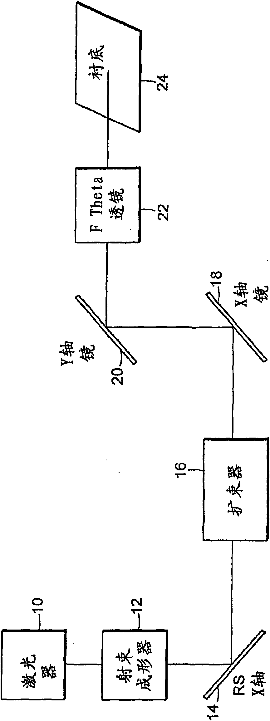
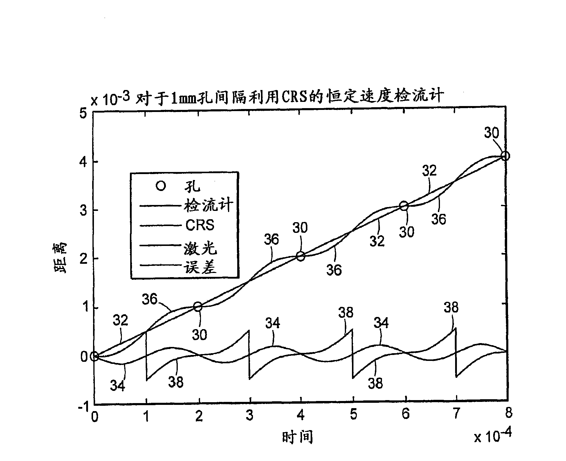
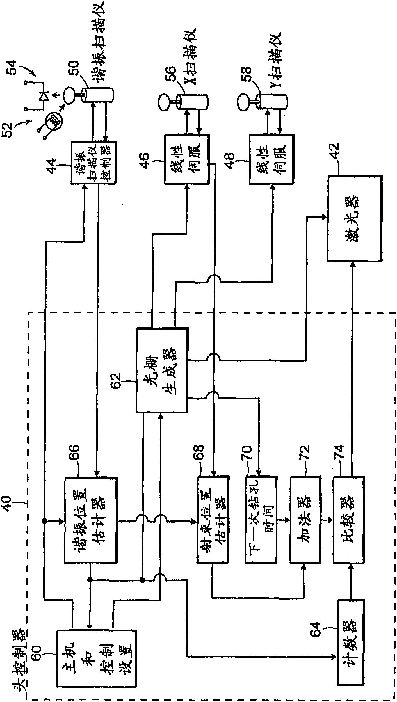
[0016] In many applications, the regions of the target substrate to be drilled with holes are arranged such that there will be clusters of closely spaced holes along a row, where the spacing is much smaller than the field size. In these cases, it is possible to use limited rotation motors in constant speed mode combined with high speed scanners to produce faster drilling rates. The scanner can be an acousto-optic deflector, an electro-optic deflector, a rotating polygon, an additional galvanometer optical scanner, or a resonant scanner.

[0017] Additional scanners require high speed but much smaller angular path, so placement in front of a beam expander requiring a small aperture may be optimal in certain applications. Overall, the amount of time a mirror can move is proportional to the size of the aperture. Smaller aperture, higher speed systems can be provided by placing high speed scanning elements in front of the beam expander. Other advantages of such a system include ...


PUM


Abstract

A laser processing system is disclosed for providing a relatively small velocity of a laser beam at target location while at least one scanner scans at a relatively larger velocity. The system includes a laser source, a first scanning unit, a beam expander, a second scanning unit and focusing optics. The laser source is for providing a pulsed laser output having at least one beam with a beam dimension. The first scanning unit is for scanning the laser output in a first direction along a first axis at the target location. The beam expander is for receiving the laser output and for modifying a beam diameter of the laser output and providing a modified laser output. The second scanning unit is for scanning the modified laser output from the beam expander in a second direction along the first axis at the target location. The second direction is substantially opposite to the first direction along the first axis such that a net velocity of the modified laser output along the first axis at the target location may be made to be effectively zero during a laser pulse. The focusing optics is for focusing the modified laser output toward the target location.

Description

[0001] priority [0002] This application claims priority to US Provisional Patent Application Serial No. 60 / 839,211, filed August 22, 2006. technical field [0003] The present invention relates generally to laser processing systems for providing drilled holes in printed circuit boards, and more particularly to such laser processing systems providing improved speed and accuracy in the processing of printed circuit boards. Holes may be used to provide paths (or vias) through the circuit board. Background technique [0004] It is known that laser drilling is often performed using a laser beam positioned with an optical scanner, such as a galvanometer optical scanner. Galvanometric optical scanners typically include a scanning mirror coupled to a limited rotation motor. Such scanners are commonly referred to as "galvanometers" or "galvanometer scanners," and examples of such scanners are disclosed in US Patent No. 6,424,632, assigned to the assignee of the present invention....

Claims


Application Information

Patent Timeline
IPC IPC(8): B23K26/38
CPCG02B26/105B23K26/0807G02B26/101B23K26/381B23K26/063B23K26/4075B23K26/40B23K26/0622B23K26/082B23K26/382B23K2103/50B23K26/60G02B26/10H01S3/10
Inventor A·I·皮纳德K·佩尔苏F·斯图卡林
Owner 诺万达公司
Why Eureka
Try Eureka