Al technical title is built by PatSnap Al team. It summarizes the technical point description of the patent document.
A forming machine and hydraulic technology, which is applied in the production of gas pipe connecting elbows and elbow forming machines, can solve the problems of poor forming quality and low single-station efficiency, and achieve good forming quality, stable transmission and stable process Effect
Active Publication Date: 2010-10-06
江阴三本机械科技有限公司
View PDF0 Cites 0 Cited by
Summary
Abstract
Description
Claims
Application Information
AI Technical Summary
This helps you quickly interpret patents by identifying the three key elements:
Problems solved by technology
Method used
Benefits of technology
Problems solved by technology
Before this invention, most of the previous elbow forming machines were mechanical, with poor forming quality and low single-station efficiency.
Method used
Image
Click on the blue label to locate the original text in one second.
Reading with bidirectional positioning of images and text.
Examples
Embodiment Construction
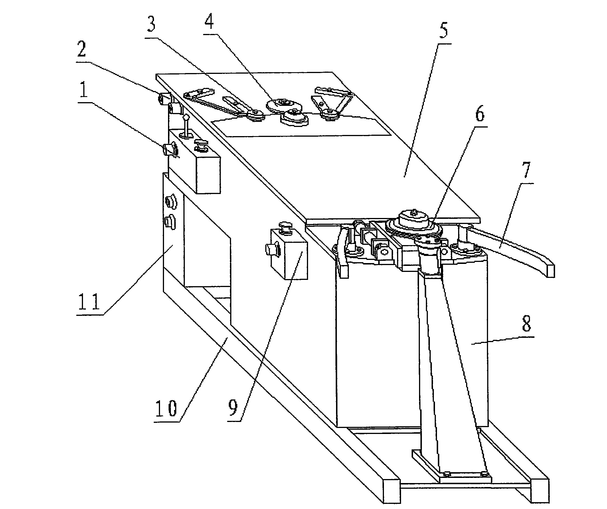
[0026] see figure 1 , the air duct hydraulic elbow forming machine of the present invention mainly consists of a frame 10, a box body 8, a working table 5, a table lifting mechanism 2, a flanging mechanism 4, a flanging press wheel mechanism 3, a forming engagement mechanism 6, and a forming bracket 7. The flanging control electric box 1, the forming control electric box 9 and the host electric control system 11 are composed. Described box body 8 is installed on the frame 10, and work table top 5 is installed on the box body 8 by table top elevating mechanism 2, and flanging mechanism 4 is installed in the middle of work table top 5, and flanging press wheel mechanism 3 has two pieces, is installed on On the worktable 5 on the left and right sides of the flanging mechanism 4, the forming engagement mechanism 6 is installed on the box body 8 and the frame 10, and placed on the side of the worktable 5, and the forming bracket 7 has two pieces, which are installed on the forming ...
PUM
Abstract
The invention relates to a duct hydraulic-bend forming machine comprising a stand (10), a box body (8), a work table top (5), a table top lifting mechanism (2), a flanging turner (4), a flanging clamping wheel mechanism (3), a forming occlusion mechanism (6) and a forming bracket (7), wherein the flange turner (4) comprises a mounting stand (4.10), a connecting mounting seat (4.7), a sliding guide (4.8), a fixed seat (4.5), a movable seat (4.2), a hydraulic motor I (4.1), a hydraulic motor II (4.6), a flanging wheel I (4.3), a flanging wheel II (4.4) and a push action cylinder (4.9); the forming occlusion mechanism comprises a mounting stand (6.6), a positioning guide rod (6.3), a mounting seat (6.5), a movable support (6.4), a hydraulic motor (6.8), an occlusion oil cylinder (6.10), a power transmission wheel (6.9), an up-down forming wheel (6.2), a push action cylinder (6.7) and a depended wheel mechanism (6.1). The invention has the advantages that the transmission is smooth and soft by utilizing the characteristic of the hydraulic system transmission so as to enable the whole workpiece processing procedure to be stable, reduces rejection rate, has good forming quality and greatly enhances the working efficiency with double stations.
Description
(1) Technical field [0001] The invention relates to an elbow forming machine matched with a spiral gas pipe. It is widely used in the production of gas pipe connecting elbows. It belongs to the technical field of pipe making machines. (2) Background technology [0002] With the emergence of new spiral ducts, the manufacturing technology of connecting elbows also needs to be continuously improved. The hydraulic elbow forming machine is a special equipment for the manufacture of air duct elbows. Before the present invention, most of the previous elbow forming machines were mechanical, with poor forming quality and low single-station efficiency. (3) Contents of the invention [0003] The object of the present invention is to overcome the above disadvantages and provide a hydraulic elbow forming machine for air ducts with good forming quality and high efficiency. [0004] The object of the present invention is achieved in the following way: an air duct hydraulic elbow form...
Claims
Application Information
Patent Timeline
Application Date:The date an application was filed.
Publication Date:The date a patent or application was officially published.
First Publication Date:The earliest publication date of a patent with the same application number.
Issue Date:Publication date of the patent grant document.
PCT Entry Date:The Entry date of PCT National Phase.
Estimated Expiry Date:The statutory expiry date of a patent right according to the Patent Law, and it is the longest term of protection that the patent right can achieve without the termination of the patent right due to other reasons(Term extension factor has been taken into account ).
Invalid Date:Actual expiry date is based on effective date or publication date of legal transaction data of invalid patent.