
Absorption type heat pump

An absorption heat pump and absorber technology, which is applied in the field of absorption heat pumps, can solve problems such as ineffective use of secondary heat sources and heat reduction, and achieve the effects of preventing rapid changes, suppressing temperature rise, and high thermal efficiency

Inactive Publication Date: 2009-09-30
SANYO ELECTRIC CO LTD
View PDF1 Cites 6 Cited by
  • Summary
  • Abstract
  • Description
  • Claims
  • Application Information

AI Technical Summary

Problems solved by technology

[0007] In addition, if it is difficult to absorb refrigerant vapor in the absorber 5, the amount of heat absorbed from the heat source water as a sub heat source passing through the heat transfer tubes in the evaporator 4 decreases, and the heat of the sub heat source cannot be effectively used.

Method used


Image

  • Absorption type heat pump
  • Absorption type heat pump

Examples


Embodiment Construction

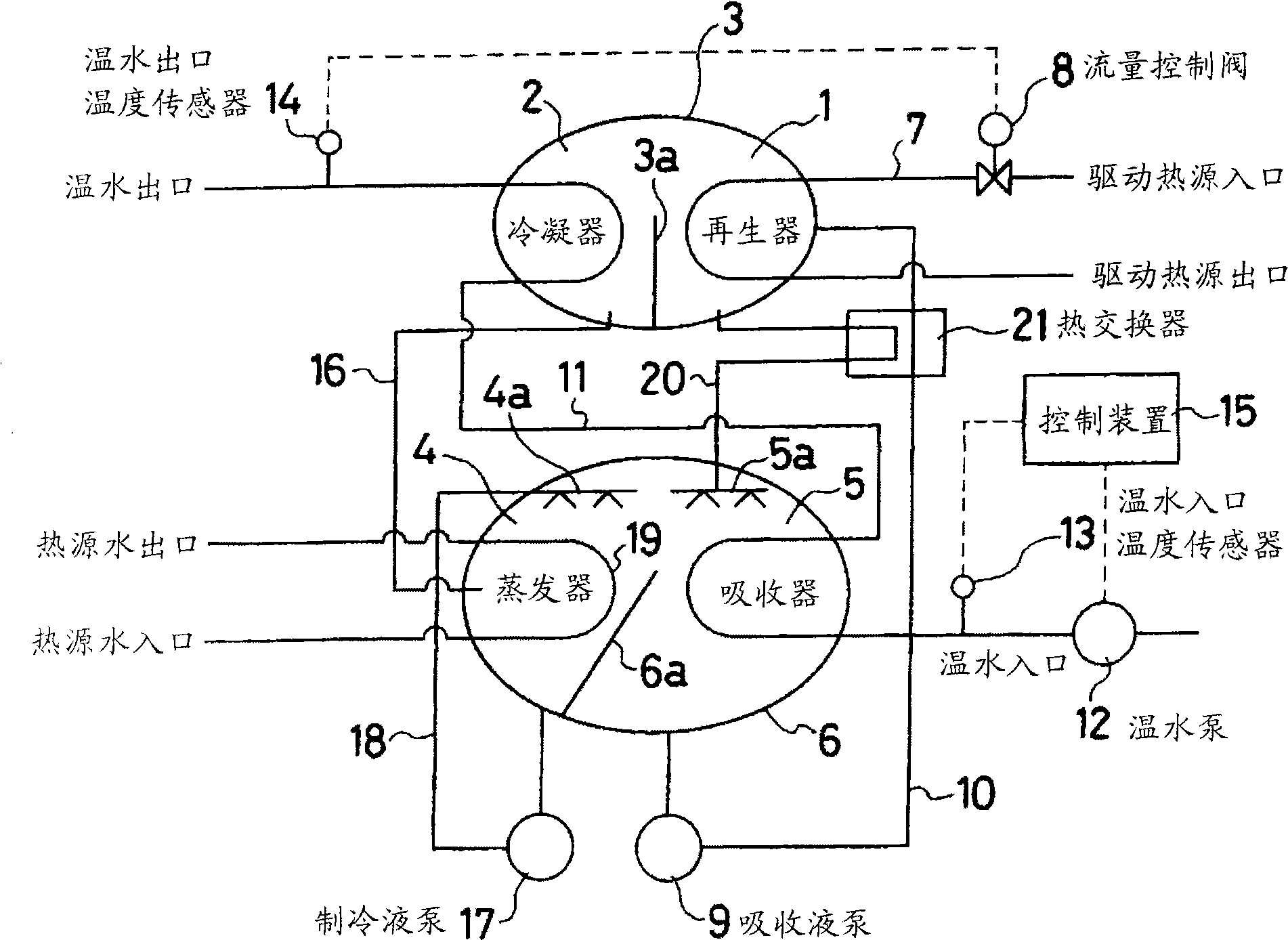
[0031] Hereinafter, embodiments of the absorption heat pump of the present invention will be described with reference to the drawings. figure 1 It is a configuration diagram showing the main part of an embodiment of the absorption heat pump of the present invention. in figure 1 Here, reference numeral 1 is a regenerator, and reference numeral 2 is a condenser, which are housed in the upper body 3 and the lower part is partitioned by a partition plate 3a. Reference numeral 4 is an evaporator, and reference numeral 5 is an absorber, which are housed in the lower body 6 and the lower part is partitioned in an inclined state by a partition plate 6a.


PUM


Abstract

The invention provides an absorption type heat pump, wherein even partial load is generated in the heating operation, temperature uprising of the warm water at the warm water pipe inlet side can be suppressed. The absorption type heat pump comprises a regenerator for separating refrigerant steam by heating dilute absorption liquid returned by the absorber; a condenser for condensing and liquefying the refrigerant delivered from the regenerator; an evaporator for evaporating refrigerant delivered from the condenser; an absorber for absorbing refrigerant steam delivered from the evaporator. A warm water inlet temperature sensor through the upstream side of the warm temperature pipe of the condenser, and the absorber is disposed behind the absorber. When the warm water inlet temperature sensor detects that the temperature is over the set temperature, flow of warm water to the warm water pipe is reduced. A warm water pump is disposed on the upstream side of the absorber, which controls the flow through a control device according to a detection signal from the warm water inlet temperature sensor.

Description

Technical field [0001] The present invention relates to an absorption heat pump, which can perform original high-efficiency operation as a heat pump even when it becomes a partial load. Background technique [0002] Conventionally, there has been known an absorption heat pump using water as a refrigerant and a lithium bromide (LiBr) solution as an absorption liquid, for example. The absorption heat pump has as its main components: a regenerator, which heats the dilute absorption liquid returned from the absorber to separate refrigerant vapor; and a condenser, which condenses the refrigerant vapor sent from the regenerator And liquefaction; the evaporator, which stores the refrigerant sent from the condenser, and spreads it from the diffuser to the heat transfer tube to evaporate; the above-mentioned absorber, which passes the concentrated absorption liquid sent from the regenerator The refrigerant vapor sent from the evaporator is dispersed and absorbed from the diffuser (for exa...

Claims


Application Information

Patent Timeline
Patent Type & Authority Applications(China)
IPC IPC(8): F25B15/02F25B49/04
CPCY02B30/62Y02A30/27
Inventor 石河豪夫山崎志奥梨本猛夫小林唯人西田一孝
Owner SANYO ELECTRIC CO LTD
Learn More