

Fin structure for air-conditioning evaporators
An evaporator and fin technology, which is applied in the field of heat exchangers, can solve the problems of reduced heat exchange efficiency, reduced heat exchange volume, and large thickness of condensed water liquid film, so as to increase heat exchange volume, good effect, and improve heat exchange efficiency effect
Inactive Publication Date: 2009-09-30
HUAERDA CHINA AUTOMOBILE AIR CONDITIONING
View PDF1 Cites 0 Cited by
- Summary
- Abstract
- Description
- Claims
- Application Information
AI Technical Summary
Problems solved by technology
However, in this evaporator, the condensed water passes through, and the liquid film thickness of the condensed water is relatively large, resulting in a decrease in the heat exchange amount and a decrease in the heat exchange efficiency.
Method used
View moreImage
Smart ImageViewing Examples

Examples
Embodiment Construction
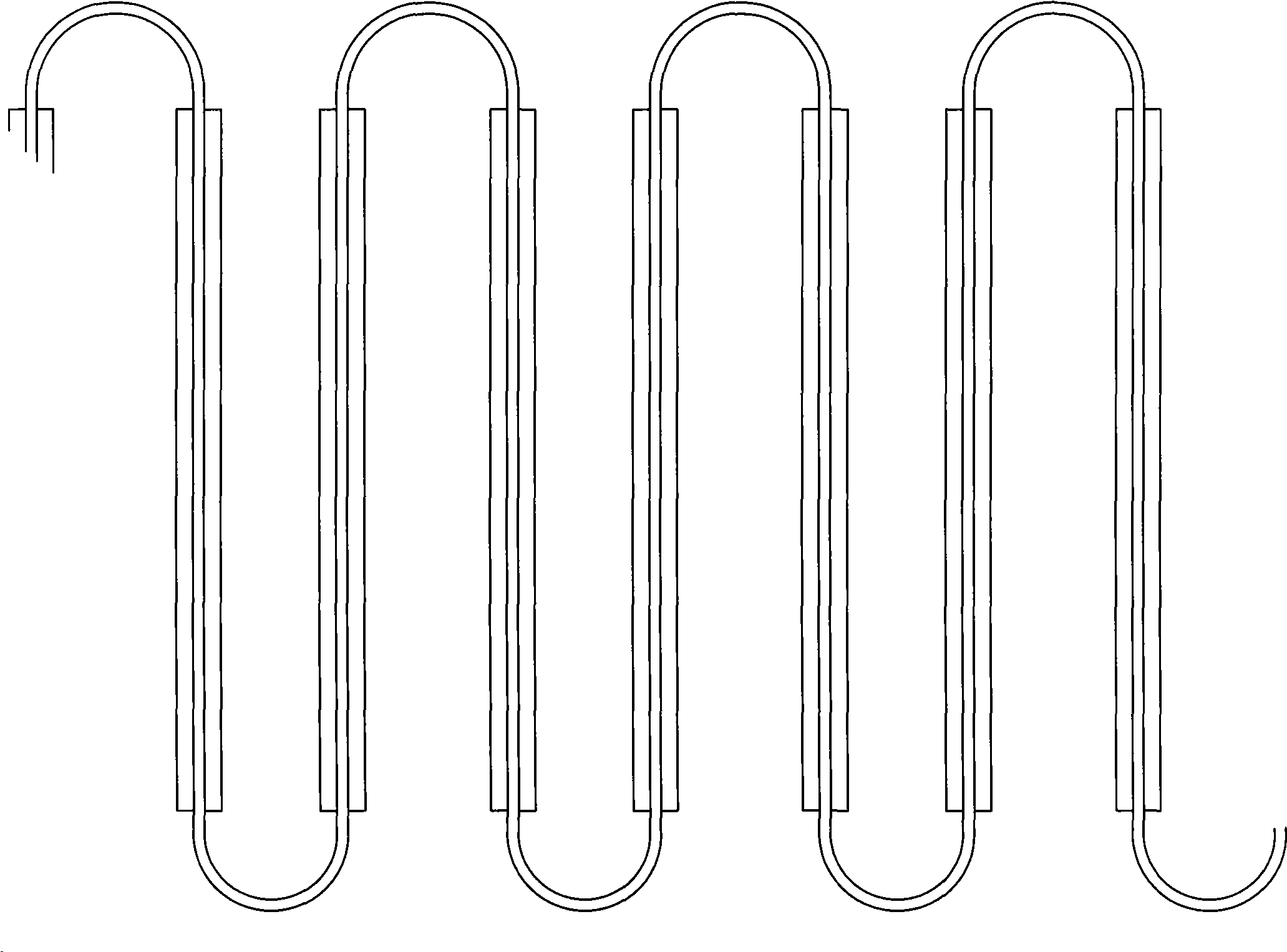
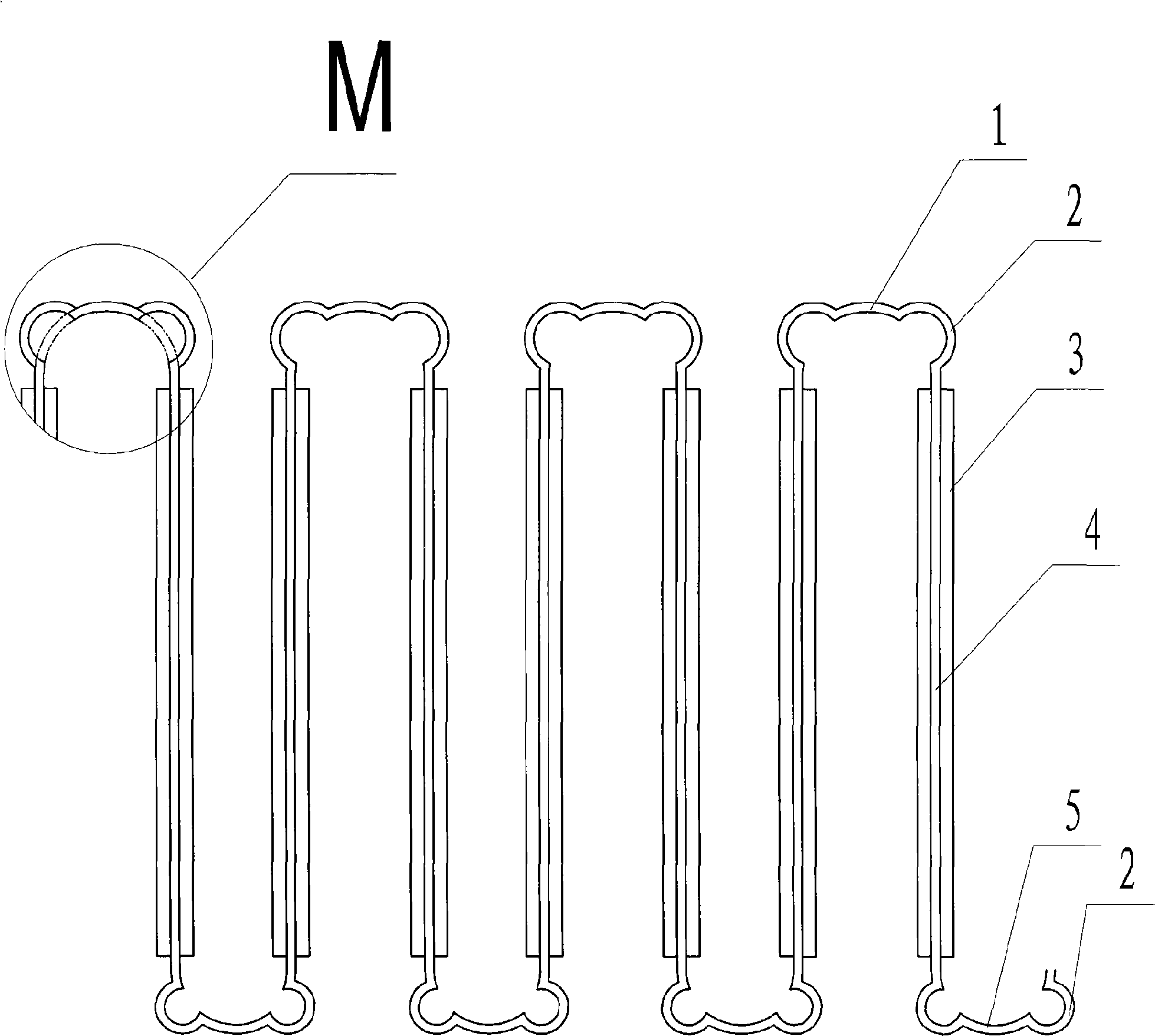
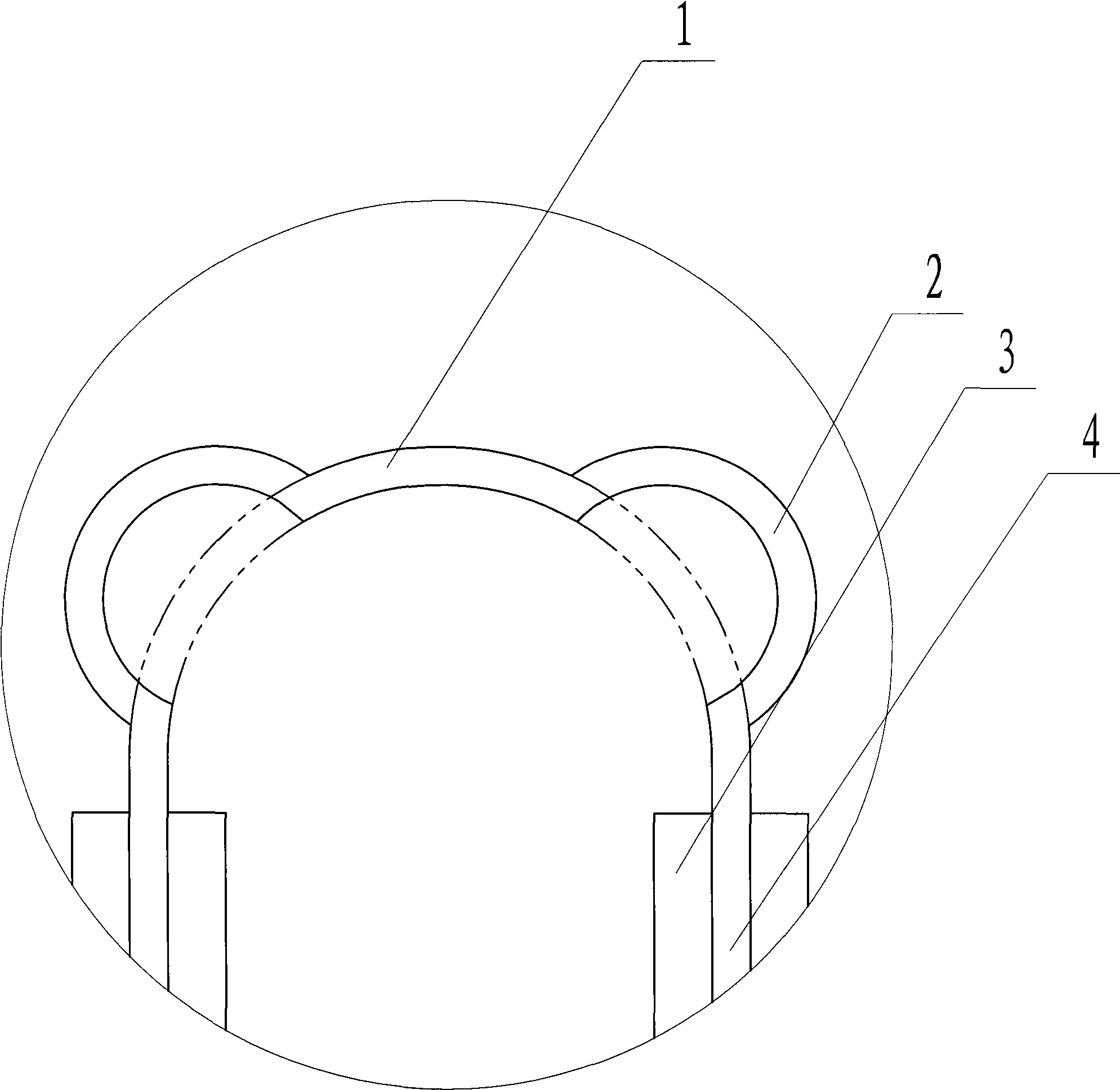
[0010] Refer to the attached figure 2 , figure 2 It is a top view after the fins are folded. The fin structure of this air-conditioning evaporator has a base body 4 on which louvers 3 are equidistantly arranged. Fins with crests 1 and troughs 5 are formed, and arc-shaped protrusions 2 are arranged at the crests 1 or troughs 5; the arc-shaped protrusions 2 are arranged symmetrically along the center line of the shutter substrate. The fins of this structure can reduce the liquid film thickness of the condensed water, thereby increasing the heat exchange amount and improving the heat exchange efficiency.
Login to View More PUM
 Abstract
The invention discloses a fin structure for air-conditioning evaporators, which is provided with a basal body (4), wherein shutters (3) are arranged on the basal body (4) in equidistance; the basal body is folded along base materials between the shutters so as to form fins having wave crests (1) and wave troughs (5). The structure is characterized in that the wave crests or the wave troughs are provided with circular arc shape protrusions (2). The evaporator fins in the structure used on an air conditioner can reduce the thickness of a condensed-water liquid film, increase the amount of heat exchange and improve the efficiency of heat exchange.
Description
technical field [0001] The invention relates to a heat exchanger for an air conditioner, in particular to fins of an evaporator. Background technique [0002] At present, the structure of the evaporator on the air conditioner is various. Its function is to absorb and evaporate the low-temperature and low-pressure refrigerant inside, so as to take away the heat of the cold storage to achieve the purpose of cooling. The most commonly used evaporator is composed of tubes and fins. , check the Chinese patent database, wherein the publication number is CN1782607A, and the title of the invention is "Air Conditioner Heat Exchanger Fin Structure", which discloses the following content: A fin structure of an air conditioner heat exchanger is connected by multi-layer fins with holes The round-shaped refrigerant pipe is formed by welding, and a plurality of parallel fins are punched with a punch between the refrigerant pipes on each fin. The feature is that the parallel fins on the fin...
Claims
Login to View More Application Information
Patent Timeline
 IPC IPC(8): F28F3/00F28F13/04F25B39/02
Inventor田晓虎贾李澄
OwnerHUAERDA CHINA AUTOMOBILE AIR CONDITIONING