
Heat exchanger for new energy sources

A heat exchanger, new energy technology, applied in the direction of heat exchanger fixing, heat exchange equipment, heat exchanger type, etc., can solve the problems of uneven battery temperature, large battery charge and discharge heat, and electric heating film easy to short circuit. , to achieve the effect of reducing material and processing costs and increasing heat exchange

Pending Publication Date: 2019-11-29
四川赛特制冷设备有限公司
View PDF0 Cites 0 Cited by
  • Summary
  • Abstract
  • Description
  • Claims
  • Application Information

AI Technical Summary

Problems solved by technology

Such a single cooling and heating is not convenient for the thermal management of new energy vehicles
At the same time, due to the increasing mileage and the battery capacity of new energy vehicles, the heat generated by charging and discharging the battery is large, and a special cooling system is needed for cooling. At the same time, when the ambient temperature of the battery is low, the battery cannot Charging and discharging, the traditional method adopts the internal electric heating method of the battery to heat up, but the electric heating film is easy to short circuit, resulting in heating aging, and the internal temperature of the battery is not uniform during electric heating, which makes the battery unable to reach the best use state, and the battery also needs special heating system, and the thermal management of the battery is to combine the cooling and heating systems of the battery into a constant temperature system, and exchange heat and cold through thermal fluid

Method used


Image

  • Heat exchanger for new energy sources
  • Heat exchanger for new energy sources
  • Heat exchanger for new energy sources

Examples


Embodiment

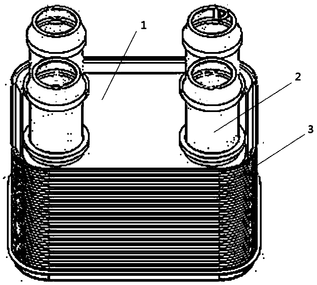
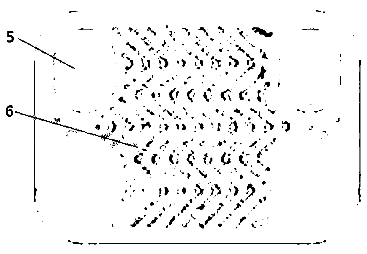
[0025] Such as Figure 1~5 As shown, a heat exchanger for new energy includes an exchanger main body 1 and a liquid collecting pipe 2 formed by stacking a plurality of forming plates 3 left and right; Four liquid collection holes 5 and ribs 4 formed by stamping on the surface of the forming plate 3; the liquid collection holes 5 after the multiple forming plates 3 are stacked left and right form a liquid collection channel, and the liquid collection channel and the liquid collection pipe 2 Sealed connection; the ribs 4 stacked after the plurality of forming plates 3 turn left and right form a flow channel 6 .

[0026] The forming plate 3 is a 0.4mm double composite layer 3-series aluminum plate with a length of 90mm, a width of 65mm and a thickness of 0.3mm.

[0027] The stack height of the heat exchanger main body 1 is 50 mm.

[0028] The height of the rib shape 4 is 0.6mm.

[0029] The sides of the forming plate 3 are inclined to be folded, and the angle of the folded edg...


PUM

PropertyMeasurementUnit
Lengthaaaaaaaaaa
Widthaaaaaaaaaa
Thicknessaaaaaaaaaa

Abstract

The invention discloses a heat exchanger for new energy sources. The heat exchanger comprises a heat exchanger main body and a liquid collecting pipeline, wherein the heat exchanger main body is formed by enabling a plurality of molding plates to be turned leftwards and rightwards and then overlapping the molding plates; the molding plates are equipped with four liquid collecting holes which are formed in the four corners of the molding plates and rib molds which are positioned on the surfaces of the molding plates and are molded through a punching manner; a liquid collecting channel is formedthrough the liquid collecting holes which are formed by enabling the plurality of the molding plates to be turned leftwards and rightwards and then overlapping the molding plates, and the liquid collecting channel is hermetically connected with the liquid collecting pipeline; and a flow channel is formed by the rib molds which are formed by enabling the plurality of the molding plates to be turned leftwards and rightwards and then overlapping the molding plates. The heat exchange ability is high, so that the heat exchanging ability of the heat exchanger which is formed by welding the moldingplates with the length and width sizes being 90*65mm and the overlapping heights being 50mm can be up to 5KW. Compared with the conventional heat exchanger, the heat exchanger disclosed by the invention has the advantages that inner fins of an oil cooler structure are eliminated, and the material and processing costs are reduced.

Description

technical field [0001] The invention relates to the technical field of new energy heat exchangers, in particular to a new energy heat exchanger. Background technique [0002] With the development of new energy vehicles, the heating of new energy vehicles can no longer use the heat exchange of engine cooling water to provide heat to the passenger compartment in the traditional way of fuel vehicles. At present, new energy vehicles mainly heat the passenger compartment through PTC heating, while refrigeration is directly refrigerated by replacing the traditional automotive air-conditioning refrigeration system compressor with an electric compressor. Such a single cooling and heating is not convenient for the thermal management of new energy vehicles. At the same time, due to the increasing mileage and the battery capacity of new energy vehicles, the heat generated by charging and discharging of the battery is large, and a special cooling system is needed for cooling. At the sa...

Claims


Application Information

Patent Timeline
IPC IPC(8): F28D9/00F28F3/04F28F3/08H01M10/613H01M10/615H01M10/625H01M10/6556H01M10/6567
CPCF28D9/00F28F3/04F28F3/08H01M10/613H01M10/615H01M10/625H01M10/6556H01M10/6567F28F2275/06Y02E60/10
Inventor 杨顺福
Owner 四川赛特制冷设备有限公司
Learn More