
Battery device for ventilation system

A technology for battery devices and ventilation systems, applied in ventilation systems, energy recovery systems for ventilation and heating, air conditioning systems, etc., can solve the problems of high cost and time required by traditional systems, reduce demand, promote additional recirculation, large The effect of heat exchange

Pending Publication Date: 2022-03-18
NZXT CORP
View PDF0 Cites 0 Cited by
  • Summary
  • Abstract
  • Description
  • Claims
  • Application Information

AI Technical Summary

Problems solved by technology

[0011] There is also a problem in the prior art that manufacturing, assembling and installing conventional systems with filters and battery cells takes time and results in high costs

Method used


Image

  • Battery device for ventilation system
  • Battery device for ventilation system
  • Battery device for ventilation system

Examples


Embodiment Construction

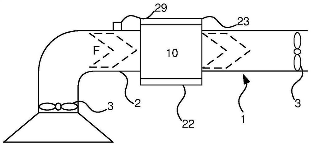
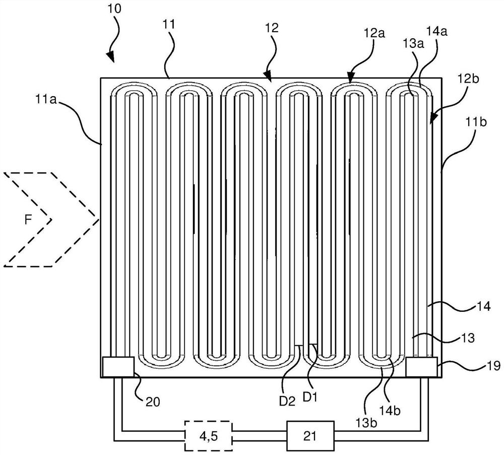
[0067] With reference to the accompanying drawings, figure 1 is a schematic side view of a ventilation system 1 with a duct 2 and a battery arrangement 10 arranged along the duct 2 such that the duct 2 can guide exhaust gases through the battery arrangement 10 . Such a ventilation system 1 may be of any known type and is not limited to the characteristics of the battery device 10 . The ventilation system 1 may even be located in environments where the exhaust gas contains unwanted particles such as grease, animal oil, dust, salt, lint or other particle types that need to be effectively managed. Such an environment could be, for example, a marine environment, a drying system or a large restaurant kitchen, a bakery or any other environment where unwanted particles are generated during use.

[0068] These types of particles can be of different sizes and shapes. The typical particle size range for more than 95% of the sample mass of troublesome pollutants is 2 μm to 25 μm.

[0...


PUM


Abstract

A heat exchanger (10 ') arranged to exchange energy with a gas flow (F), the heat exchanger (10') comprising: a housing (11) arranged to receive the gas flow (F) through a first end (11a); at least one conduit arrangement (12) arranged within the housing (11) such that the air flow (F) will pass along the conduit arrangement (12) when the air flow (F) is received through the housing (11) wherein the heat exchanger (10 ') is arranged for use in a system in which air carries particles, such as a marine environment, a kitchen system or a drying system.

Description

technical field [0001] The present invention relates to a battery unit for a ventilation system, in particular to a ventilation system in environments where particles are present in the exhaust air, and especially to a battery unit in a ventilation system, especially in marine environments, kitchens Ventilation systems in environments, textile drying environments, or other systems with airborne particles. Background technique [0002] Energy recirculation is deployed in most ventilation systems in newer residential and office buildings that include both exhaust and supply air. The overall objective is to extract energy from the warm exhaust gas and transfer it to the cold supply air via a heat exchanger arrangement to preheat the cold supply air with the recirculated energy. For example, such a component could be a cross-flow gas-to-gas exchanger configured to transfer the inherent energy in the exhaust to the supply using metal flanges, or a rotating disk to transfer energ...

Claims


Application Information

Patent Timeline
IPC IPC(8): F28D1/047F24F12/00F28G13/00
CPCF24F12/00F28D1/0477F28D7/087F28F9/0131F28F19/02F24F8/90F28G13/005F24C15/20F24C15/2057F28D21/0003F28F21/062B33Y80/00F24F2221/22F24F12/002F28F17/00
Inventor 尼尔斯·莱克伯格汉斯·莱克伯格
Owner NZXT CORP
Learn More