Crystallizer for continuous casting

Active Publication Date: 2014-12-25
DANIELI & C OFF MEC SPA
View PDF2 Cites 1 Cited by
  • Summary
  • Abstract
  • Description
  • Claims
  • Application Information

AI Technical Summary

Benefits of technology

The invention aims to improve the quality of cast products, such as blooms or billets, by reducing rhomboidity and preventing shape deformation and cracks. This is achieved without modifying the basic structure of conventional crystallizers and limiting casting speed. The final product shape is improved, resulting in better quality and less rhomboidity.

Problems solved by technology

In the field of continuous casting, in particular in the case of casting blooms and billets, it is known that one of the main problems relating to the quality of the finished product is the defect of rhomboidity.
This defect in shape is characterized by the fact that the products, such as blooms or billets, especially for small formats cast at high speed, at the end of the solidification downstream of the casting machine do not have a profile exactly equal to the internal section of the crystallizer, but assume a rhomboidal shape which can cause problems in the subsequent rolling processes.
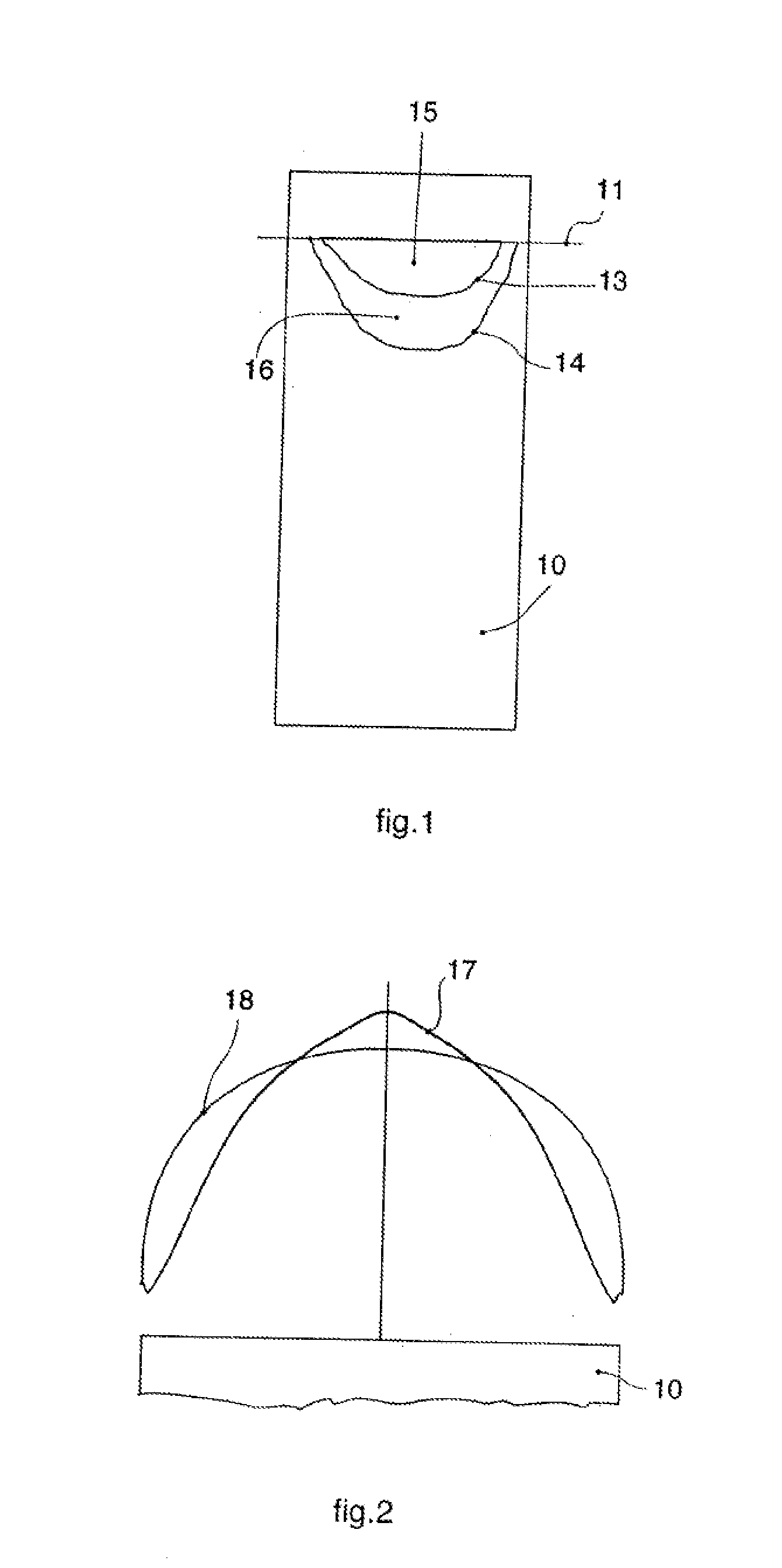
This detect in shape is usually generated because of the lack of uniformity of heat exchange in the crystallizer, in particular in the zone immediately below the meniscus, which causes an uneven thickness of skin on the perimeter, both between one side and the other of the product and also along the same side.
Once generated, the deformation increases and cannot be recovered.
A skin with a non-homogeneous thickness has weak points where the thickness is less and the formation of cracks under the skin is therefore frequent which can cause breakouts.
This problem is even more accentuated when free casting is done using oil as the lubricant.
On the other hand, if lubrication powders are used during casting, the rhomboidity is less accentuated thanks to the insulating effect of the powders and their homogeneous distribution; however, the use of powders is more costly compared to the use of oil and is therefore uneconomic when commercial steels are being produced.
Moreover, the problem increases as the casting speed increases, which puts a limit on the maximum speeds obtainable and therefore on the productivity of the casting machine.
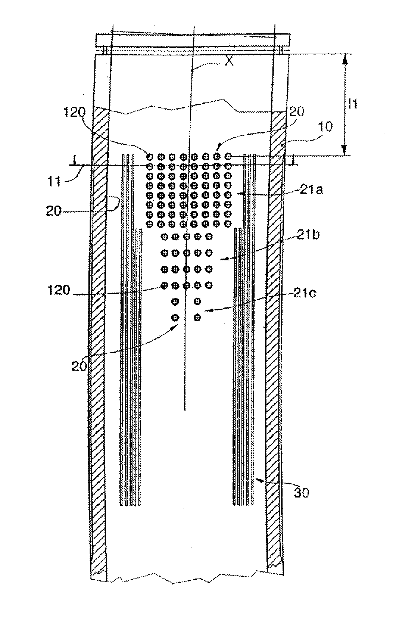
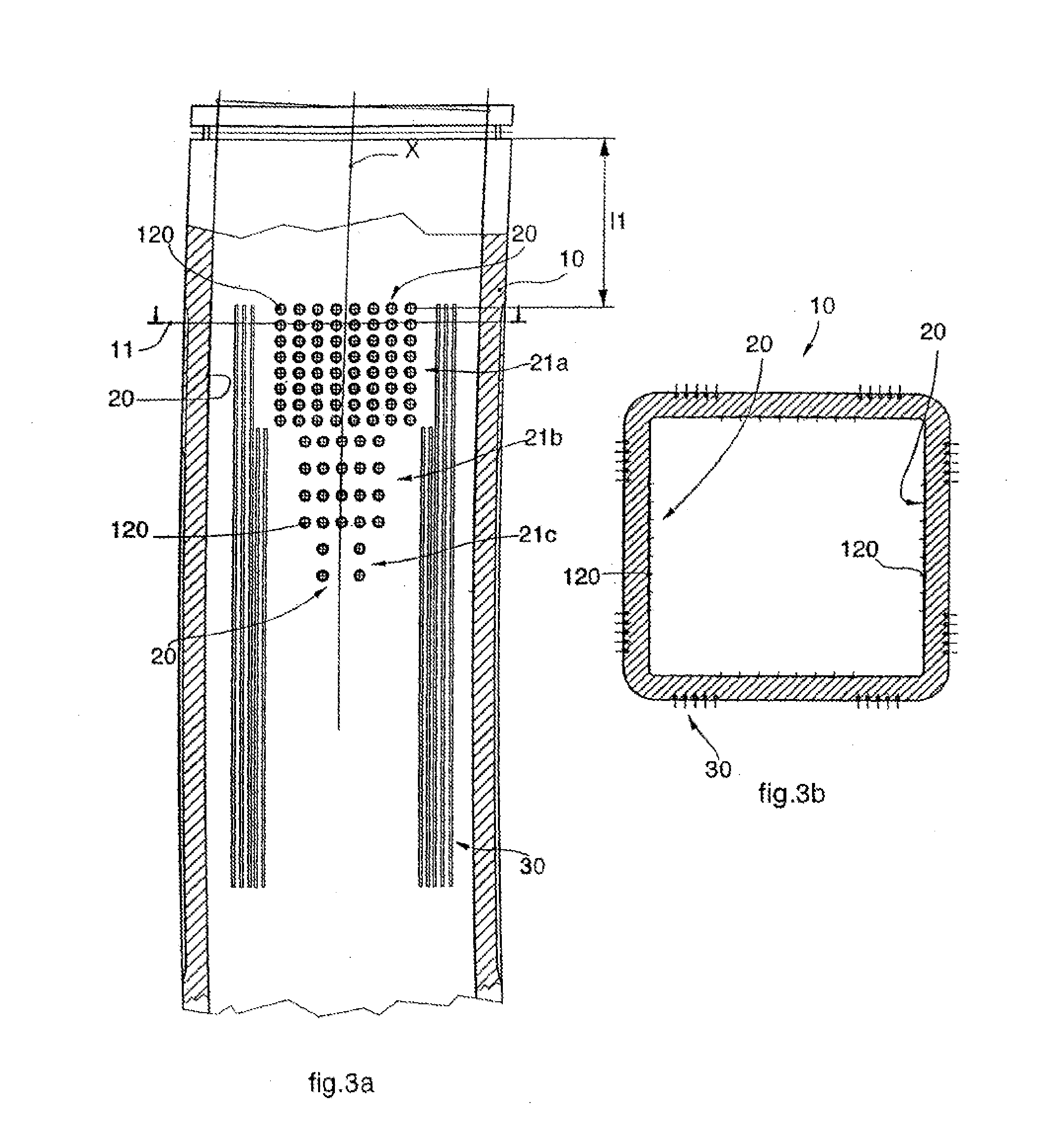
Rhomboidity is therefore a defect in shape due to uncontrolled conditions of adhesion between the liquid steel and internal walls of the crystallizer for a certain segment below the meniscus, that is at the moment when there is the greatest heat exchange and coinciding with the formation of the first skin, in which a non-uniform heat exchange occurs, and therefore a difference in thickness of the skin which is created along the perimeter of the billet as it solidifies.
This solution, even if it is an improvement, does not solve the problem on the one hand because the distribution of the concavities is not correlated to the development of the heat flow, and on the other hand because said concavities by themselves worsen the problem of the cracks under the skin and the breakouts in the more critical cases of free casting at high speed and using oil as a lubricant.
Indeed, the concavities reduce the total heat flow exchanged between steel and ingot mold and therefore the average thickness of the skin at exit from the ingot mold.
These solutions only partially reduce the problem, since in any case they create a lack of homogeneity of heat treatment on the entire perimeter of the billet.
However, the grooves are provided either on the whole face of the crystallizer or in its central zone, and they are not therefore intended to homogenize the cooling treatment in combination with other means operating in correspondence with the zone of the meniscus.

Method used


Image

  • Crystallizer for continuous casting
  • Crystallizer for continuous casting
  • Crystallizer for continuous casting

Examples


Embodiment Construction

[0037]A crystallizer 10 for the continuous casting of long products is shown schematically in FIG. 1, where the reference number 11 substantially indicates the nominal line of the meniscus of liquid metal.

[0038]In a crystallizer 10 of this type, for long products such as blooms or billets 12, of a polygonal shape, preferably quadrangular, even more preferably rectangular or square, with thin wails and cooled by means of an external jacket, the isotherm lines (at equal temperature) on the internal surface of the crystallizer 10 have, a development of the elliptical or parabolic type, like the lines 13 and 14 shown in FIG. 1.

[0039]In particular, the region indicated by the reference number 15 is that which has the maximum temperatures because it corresponds to the region of the meniscus; on the contrary, the adjacent region indicated by the reference number 16, comprised between the two isotherm lines 13 and 14, has lower temperatures.

[0040]In FIG. 2 the development of the heat flow a...


PUM

PropertyMeasurementUnit
Fractionaaaaaaaaaa
Fractionaaaaaaaaaa
Widthaaaaaaaaaa

Abstract

Crystallizer for the continuous casting of long metal products such as blooms or billets, of the type cooled by an external cooling jacket, in which, at least in the zone of maximum thermal peak, positioned around the zone of the meniscus or immediately below it, there are means present, made on the walls of the crystallizer, to condition the heat exchange between the walls of the crystallizer and the cast steel. The means to condition the heat exchange comprise concavities or depressions made on the internal wall of the crystallizer, made around the zone of maximum thermal peak, and having a distribution that, in terms of the overall area occupied by them per surface unit, is reduced until it is canceled toward the bottom at a certain distance from said zone of maximum thermal peak.

Description

FIELD OF THE INVENTION[0001]The present invention concerns a crystallizer for the continuous casting of long metal products such as blooms or billets, cooled by an external cooling jacket.[0002]The blooms or billets to which the crystallizer is preferentially applied have a square section with the length of the side equal to 120-180 mm, or rectangular with equivalent section.BACKGROUND OF THE INVENTION[0003]In the field of continuous casting, in particular in the case of casting blooms and billets, it is known that one of the main problems relating to the quality of the finished product is the defect of rhomboidity. This defect in shape is characterized by the fact that the products, such as blooms or billets, especially for small formats cast at high speed, at the end of the solidification downstream of the casting machine do not have a profile exactly equal to the internal section of the crystallizer, but assume a rhomboidal shape which can cause problems in the subsequent rolling...

Claims


Application Information

Patent Timeline
IPC IPC(8): B22D11/124
CPCB22D11/1243B22D11/041B22D11/055B22D11/07
Inventor RINALDI, MARCOMOTTA, MARCO MAURO
Owner DANIELI & C OFF MEC SPA
Why Eureka
Try Eureka