Voltage generator with dynamic resistance feedback control

A technology of voltage generator and feedback control, which is applied to control/regulation systems, conversion equipment and instruments without intermediate conversion to AC, and can solve problems such as ripple, noise, and unstable output voltage.

Inactive Publication Date: 2009-09-30
NOVATEK MICROELECTRONICS CORP
View PDF0 Cites 14 Cited by
  • Summary
  • Abstract
  • Description
  • Claims
  • Application Information

AI Technical Summary

Problems solved by technology

The feedback loop can limit the output voltage of the charge pump, but it will inevitably generate ripple, and excessive ripple will cause the output voltage to be unstable and generate noise

Method used


Image

  • Voltage generator with dynamic resistance feedback control
  • Voltage generator with dynamic resistance feedback control
  • Voltage generator with dynamic resistance feedback control

Examples


Embodiment Construction

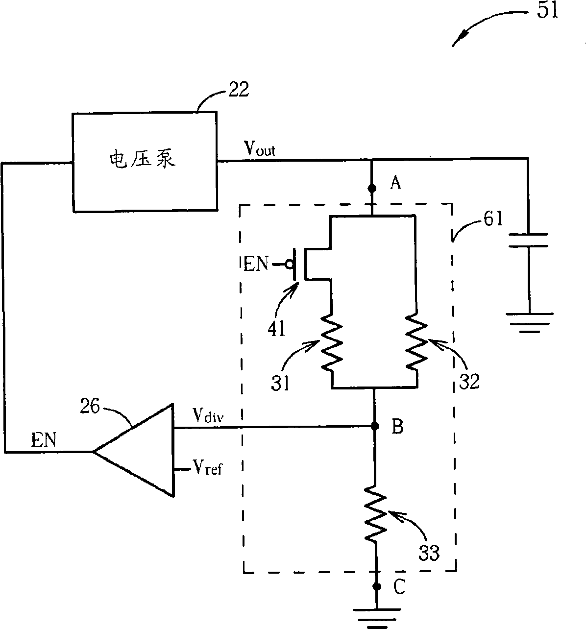
[0025] Please refer to image 3 , image 3 It is a schematic diagram of the first embodiment of the voltage generator of the present invention. The voltage generator 20 includes a charge pump 22 , a voltage dividing circuit 61 and a comparator 26 . The charge pump 22 is used to output a high voltage Vout, and the voltage divider 61 generates a divided voltage Vdiv of the high voltage Vout. The comparator 26 outputs an enable signal EN according to the divided voltage Vdiv and a reference voltage Vref. The voltage dividing circuit 61 and the comparator 26 form a feedback loop so that the charge pump 22 can adjust the high voltage Vout according to the enable signal EN. The voltage dividing circuit 61 includes a first resistor 31 , a second resistor 32 , a third resistor 33 and a first switch 41 . The first resistor 31 is coupled between a first switch 41 and a second node B, the second resistor 32 is coupled between the first node A and the second node B, and the third resi...


PUM


Abstract

The invention relates to a voltage generator with dynamic resistance feedback control. The voltage generator comprises a charge pump, a voltage division circuit and a comparator. The charge pump can output a high voltage. The voltage division circuit comprises a plurality of resistors and at least one switch, and can generate a first divided voltage of the high voltage when the switch is switched on and generate a second divided voltage of the high voltage when the switch is switched off. An output signal of the comparator can be used for controlling the switch and the charge pump, and the voltage division circuit and the comparator form a feedback loop so that the response of the comparator is quickened to reduce ripple of the high voltage output by the charge pump.

Description

technical field [0001] The invention relates to a voltage generator, in particular to a voltage generator with dynamic resistance feedback control. Background technique [0002] Please refer to figure 1 , figure 1 is a schematic diagram of a prior art voltage generator. The voltage generator 10 includes a charge pump 12 , a voltage dividing circuit 14 and a comparator 16 . The charge pump 12 is used to output a high voltage Vout, and the divided voltage Vdiv of the high voltage Vout is generated by the voltage dividing circuit 14 . The comparator 16 outputs an enable signal EN according to the divided voltage Vdiv and a reference voltage Vref. The voltage dividing circuit 14 and the comparator 16 form a feedback loop, and the charge pump 12 outputs a high voltage Vout according to the enable signal EN. The voltage dividing circuit 14 includes a first resistor 17 , a second resistor 18 and a third resistor 19 . A first terminal of the first resistor 17 is coupled to a f...

Claims


Application Information

Patent Timeline
Patent Type & Authority Applications(China)
IPC IPC(8): G05F1/46H02M3/04
Inventor 蔡宗兴
Owner NOVATEK MICROELECTRONICS CORP
Why Eureka
Try Eureka