Gantry oil-to-electricity device with automatic current-collecting cart for RTG
A gantry oil and electricity collection technology, which is applied to elevators, transportation and packaging in buildings, can solve the problems of large error reliability, low operation efficiency, poor adaptability, etc., and achieves prevention of interference, high operation efficiency, and structural compact effect
- Summary
- Abstract
- Description
- Claims
- Application Information
AI Technical Summary
Problems solved by technology
Method used
Image
Examples
Embodiment 1
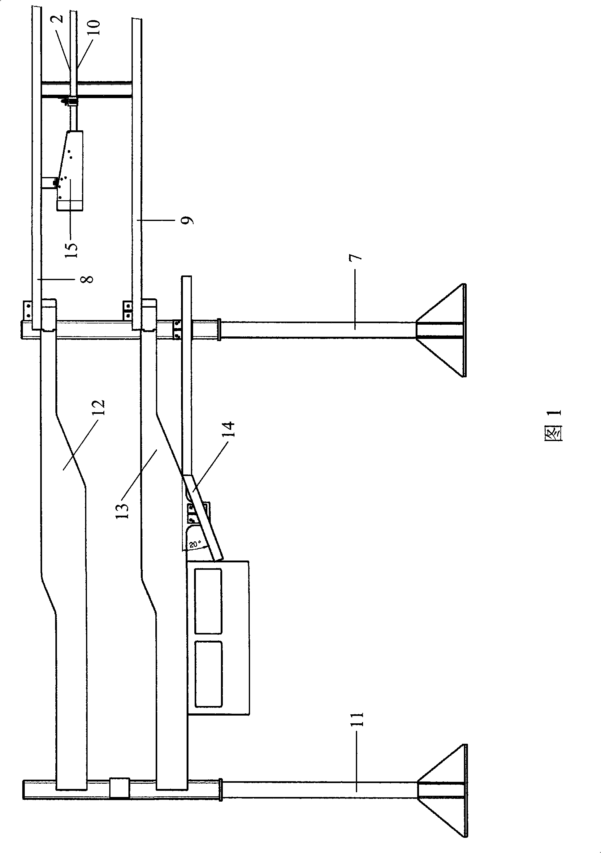
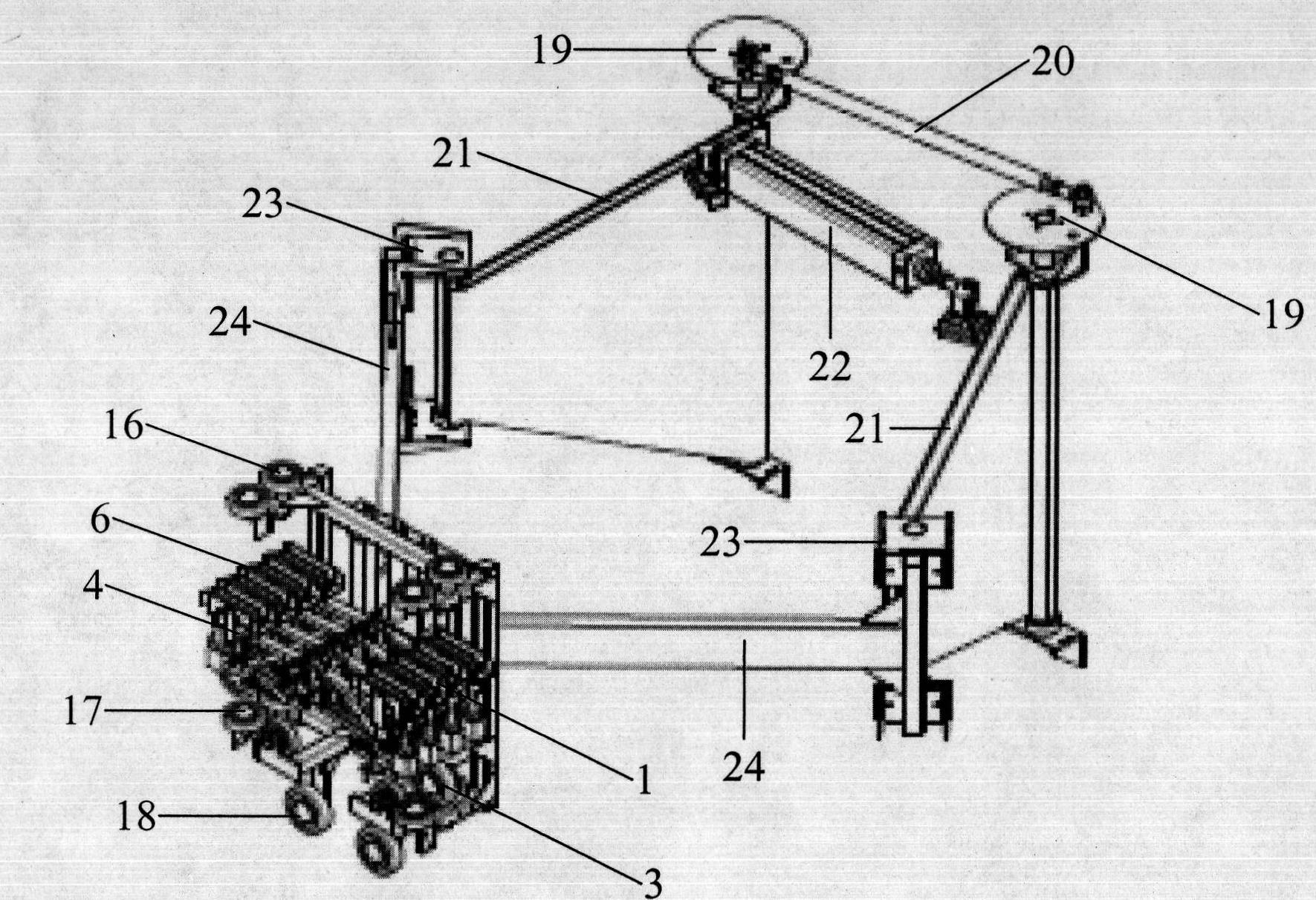
[0031] A gantry oil-to-electricity conversion device with an automatic current collection trolley for RTG, which has a gantry crane and an automatic current collection trolley. Backing plate 12, lower backing plate 13, guide plate 14, guide port 15, such as figure 1 with figure 2 As shown, the two columns 7 of the gantry frame of the gantry crane are connected by the upper rail groove 8, the bracket 10 and the lower rail groove 9, and the upper rail groove 8, the bracket 10 and the lower rail groove 9 are all placed horizontally and from top to bottom Arranged in sequence, the trolley line 2 is fixed on the bracket 10, and the trolley line 2 is respectively connected to the phase line and the neutral line of the mains power system. The lower part of the trolley 1 is equipped with a travel wheel set 3, and the travel wheel set 3 is on the lower guide rail groove 9. Rolling, fixed collector 4 on the upper part of traveling trolley 1, collector 4 is connected to power supply th...
Embodiment 2
[0038] In order to enhance the safety when taking electricity and the accuracy of control, a limit switch 25, a panel indicator light 26, a power contactor 27 and a carbon brush indicator light 28 can also be added on the automatic power collecting trolley, as Figure 5 As shown, a limit switch 25 is respectively installed on the upper and lower four corners of the traveling trolley 1, wherein the moving contacts of the upper two limit switches 25 are closed after the upper guide wheel group 16 contacts the upper backing plate 12, and the lower two limit switches 25 are closed. The moving closing contact of limit switch 25 is closed after lower guide wheel group 17 contacts lower backing plate 13, and when the moving closing contact of limit switch 25 is all closed, backing plate indicator light 26 is luminous. Such as Image 6 As shown, the moving contacts of the power contactor 27 are connected in series on the phase line. When the carbon brushes 6 are all in contact with th...
PUM
 Abstract
Description
Claims
Application Information
 - R&D
- Intellectual Property
- Life Sciences
- Materials
- Tech Scout
- Unparalleled Data Quality
- Higher Quality Content
- 60% Fewer Hallucinations
Browse by: Latest US Patents, China's latest patents, Technical Efficacy Thesaurus, Application Domain, Technology Topic, Popular Technical Reports.
© 2025 PatSnap. All rights reserved.Legal|Privacy policy|Modern Slavery Act Transparency Statement|Sitemap|About US| Contact US: help@patsnap.com


