Automatic current-collecting cart for tyre type container gantry crane

A gantry crane and container technology, which is applied to elevators, transportation and packaging in buildings, can solve the problems of large error reliability, low operation efficiency, loose structure, etc., to prevent interference, high operation efficiency and compact structure. Effect

Active Publication Date: 2009-10-07
CONDUCTIX WAMPFLER POWER & DATA TRANSMISSION EQUIP SHANGHAI +1
View PDF0 Cites 17 Cited by
  • Summary
  • Abstract
  • Description
  • Claims
  • Application Information

AI Technical Summary

Problems solved by technology

This traditional manual operation method has the following defects: 1. Loose structure: the traditional power-on method makes the design of the structure width of the ERTG take into account the factor of the traveling trolley, and prevent the gantry crane from having enough working space and not being compatible with the traveling car. The carts interact with each other, so the width is larger
2. Poor stability: The traditional manual operation method can only use manual observation method for position detection during power-on operation, which has large errors and low reliability
3. Low operating efficiency: In the traditional operating process, the gantry crane needs to wait for manual plugging and unplugging after the gantry crane arrives at the yard. The whole process takes 15 to 20 minutes, and the efficiency is low for a long time
4 Poor adaptability: Since ERTG uses high voltage and strong current, there is a risk of electric shock and leakage by manually plugging and unplugging the electric plug in rainy weather

Method used


Image

  • Automatic current-collecting cart for tyre type container gantry crane
  • Automatic current-collecting cart for tyre type container gantry crane
  • Automatic current-collecting cart for tyre type container gantry crane

Examples


Embodiment 1

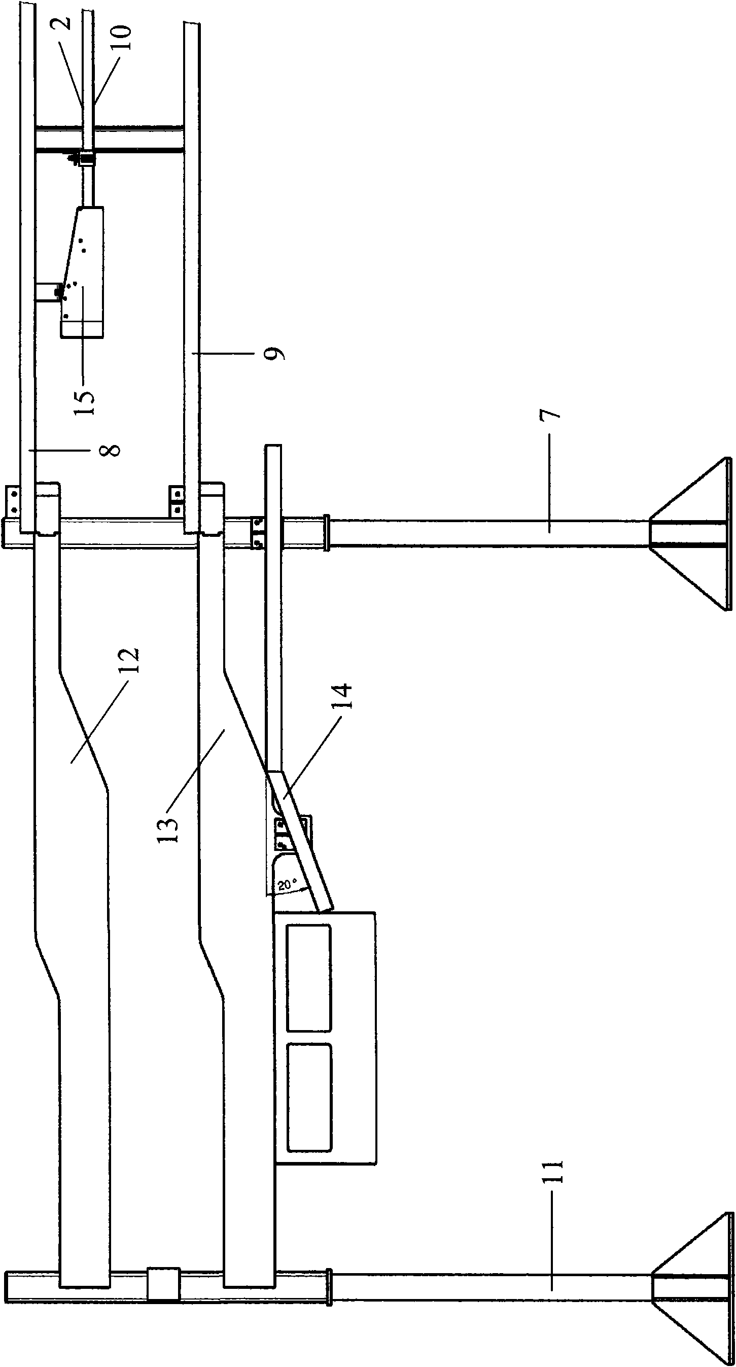
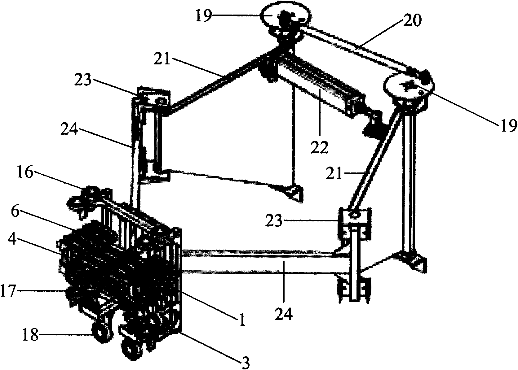
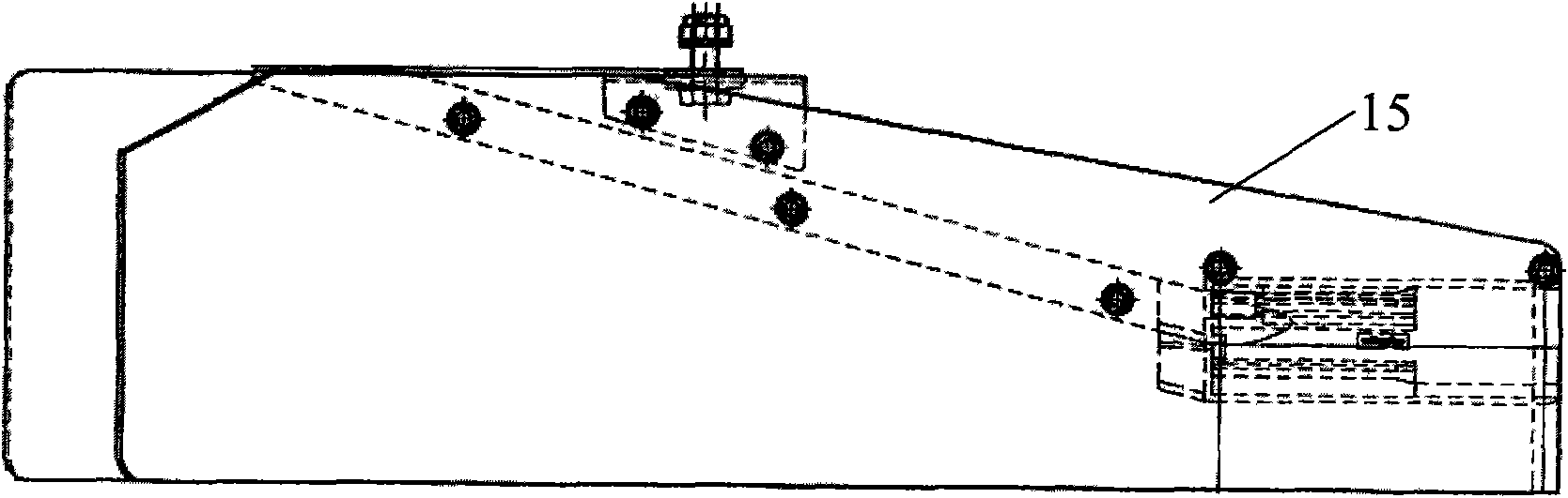
[0031] An automatic current collecting trolley for a tire-type container gantry crane, comprising a traveling trolley 1 and a trolley line 2, a stand 11, an upper backing plate 12, a lower backing plate 13, a guide plate 14, and a guide opening 15, such as figure 1 and figure 2 As shown, the two columns 7 of the gantry frame of the gantry crane are connected by the upper rail groove 8, the bracket 10 and the lower rail groove 9, and the upper rail groove 8, the bracket 10 and the lower rail groove 9 are all placed horizontally and from top to bottom Arranged in sequence, the trolley line 2 is fixed on the bracket 10, and the trolley line 2 is respectively connected to the phase line and the neutral line of the mains power system. The lower part of the trolley 1 is equipped with a travel wheel set 3, and the travel wheel set 3 is on the lower guide rail groove 9. Rolling, fixed collector 4 on the upper part of traveling trolley 1, collector 4 is connected to power supply throu...

Embodiment 2

[0038] In order to enhance the safety and accuracy when taking electricity, limit switch 25, leaning on board indicator light 26, power contactor 27 and carbon brush indicator light 28 can also be increased, as Figure 5 As shown, a limit switch 25 is respectively installed on the upper and lower four corners of the traveling trolley 1, wherein the moving contacts of the upper two limit switches 25 are closed after the upper guide wheel group 16 contacts the upper backing plate 12, and the lower two limit switches 25 are closed. The moving closing contact of limit switch 25 is closed after lower guide wheel group 17 contacts lower backing plate 13, and when the moving closing contact of limit switch 25 is all closed, backing plate indicator light 26 is luminous. Such as Figure 6 As shown, the moving contacts of the power contactor 27 are connected in series on the phase line. When the carbon brushes 6 are all in contact with the trolley line 2, that is, when the moving contac...


PUM


Abstract

The invention relates to the apparatus field along a traveling rail or a power supply line configured with conductive or insulating electric vehicle at joint or a track, specifically an automatic traveling cart for a tyre type container gantry crane. The automatic traveling cart for a tyre type container gantry crane includes a traveling cart (1) and a slide trolley wire (2), characterized in that the cart further includes a vertical bracket (11), an upper backup plate (12), a lower backup plate (13), a guide plate (14), a guide opening (15). Guide wheel groups are mounted on one side of the traveling rail (1) in parallel on upper and lower sides. Distance between the upper and lower guide wheel groups is equal to that between the upper and lower backup plates. The upper and lower guide wheel groups rotate by adhering the upper and lower backup plates. A lifting wheel group (18) is mounted on lower end of the traveling wheel group (3), the other end of which being connected with an access apparatus. The invention is compact in structure, high in stability and work efficiency, safe and reliable.

Description

technical field [0001] The invention relates to the field of arranging conductive or insulated electric vehicle power supply lines or devices along the rails along the driving rails or at their joints, in particular to an automatic current collecting trolley for a rubber-tyred container gantry crane. Background technique [0002] At present, there are two main types of lifting machinery (commonly known as yard bridges) commonly used for container yard operations in major ports in the world, one is rail-mounted container gantry cranes, namely rail-mounted gantry cranes, abbreviated as RMG, and the other is It is a tire-tyred container gantry crane, that is, mbber-tyred container gantry crane, abbreviated as RTG. RMG is powered by mains electricity, which has low energy consumption but is limited by the track and cannot be transferred. RTG has its own diesel generator set for power supply, which is flexible but consumes high energy and causes pollution. At present, a new type...

Claims


Application Information

Patent Timeline
Patent Type & Authority Applications(China)
IPC IPC(8): B66B13/12
Inventor 刘晓明
Owner CONDUCTIX WAMPFLER POWER & DATA TRANSMISSION EQUIP SHANGHAI
Why Eureka
Try Eureka