Radiator

A radiator and fin technology, applied in heat exchanger shells, indirect heat exchangers, heat exchange equipment, etc., can solve the problems of fin shaking, defective phase, fin detachment, etc.

Active Publication Date: 2011-04-27
HUIZHOU HANXU HARDWARE PLASTIC TECH CO LTD
View PDF4 Cites 0 Cited by
  • Summary
  • Abstract
  • Description
  • Claims
  • Application Information

AI Technical Summary

Problems solved by technology

[0003] The above-mentioned conventional radiators, if the combination is completed by welding, must use manufacturing processes or processing media such as electroplating, solder paste or adhesives, so they do not conform to the principle of environmental protection; and the above-mentioned prior patented technologies, or although there are Grooves are provided on the seat body for the corresponding insertion of the heat sink, but the purpose of clamping the root of the heat sink is achieved by using the compression deformation on both sides of the groove. In fact, it only deforms and closes the upper slot of the groove, so the clamp The force is only concentrated on the deformation positions on both sides of the upper notch, and at best, only two points of clamping force can be generated. Therefore, when the pressurized die stamps the upper end of the groove, the heat sink is likely to be damaged by the pre-inserted The position is not accurate, or due to the impact of vibration during stamping, the heat sink may bounce off the bottom of the groove, so the root of the heat sink is often not completely submerged in the bottom of the groove of the seat body, resulting in clamping of the root The effect is not good, not only can't be firmly and stably combined, but also the heat sinks can't be planted at the same height, resulting in a bad product with uneven distribution of heat sinks, and even the heat sinks may shake or fall off easily

Method used


Image

  • Radiator
  • Radiator
  • Radiator

Examples


Embodiment Construction

[0034] The present invention will be further described below in conjunction with the accompanying drawings and specific embodiments.

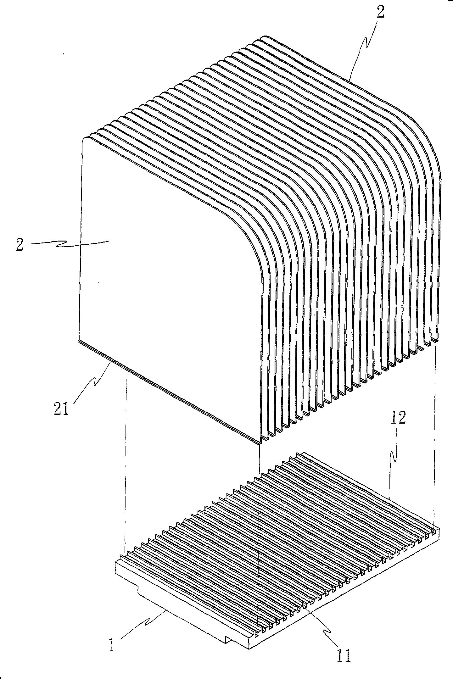
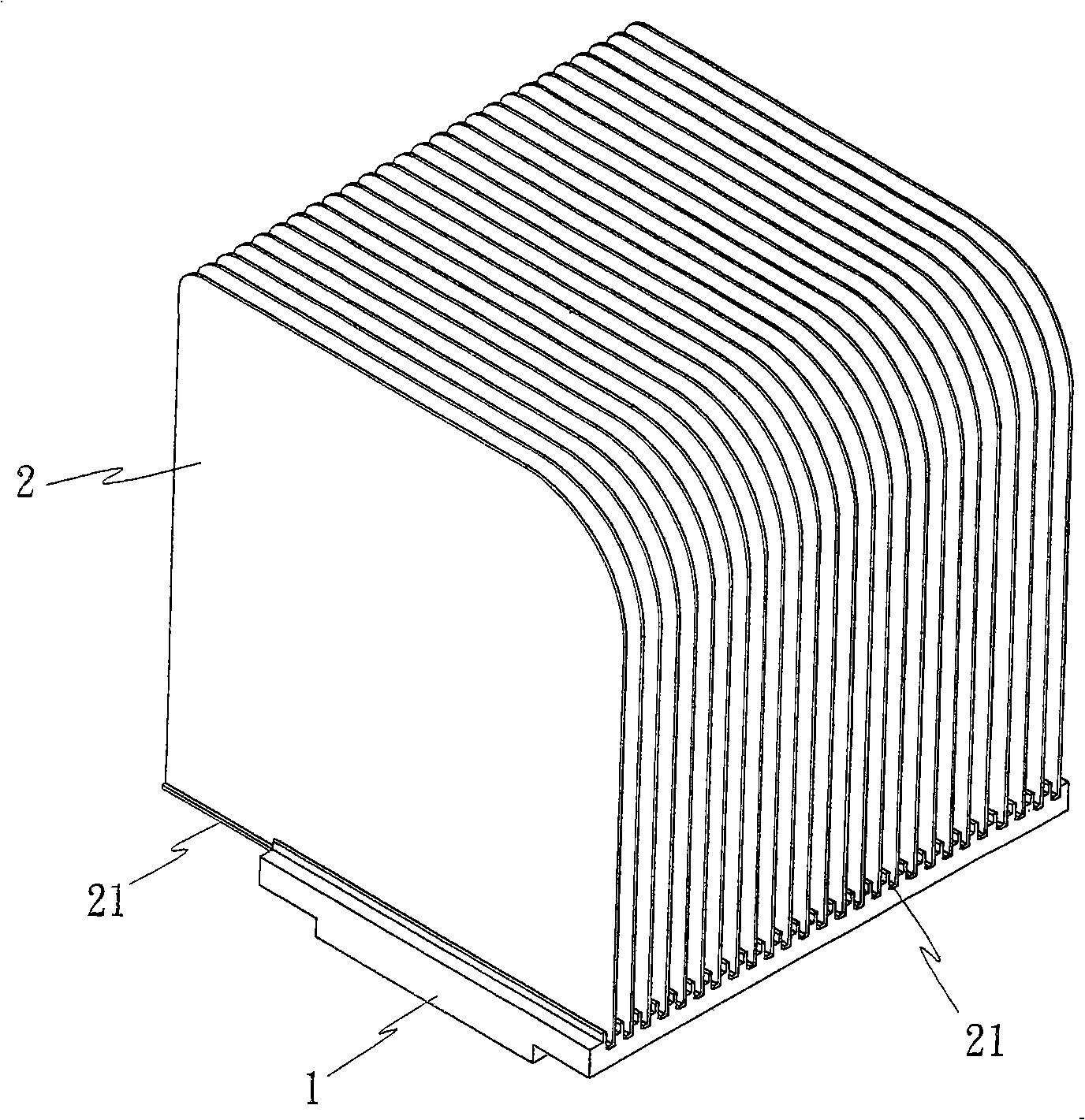
[0035] Such as figure 1 and figure 2 As shown, the radiator system of the present invention includes a base 1 and a plurality of cooling fins 2, wherein:

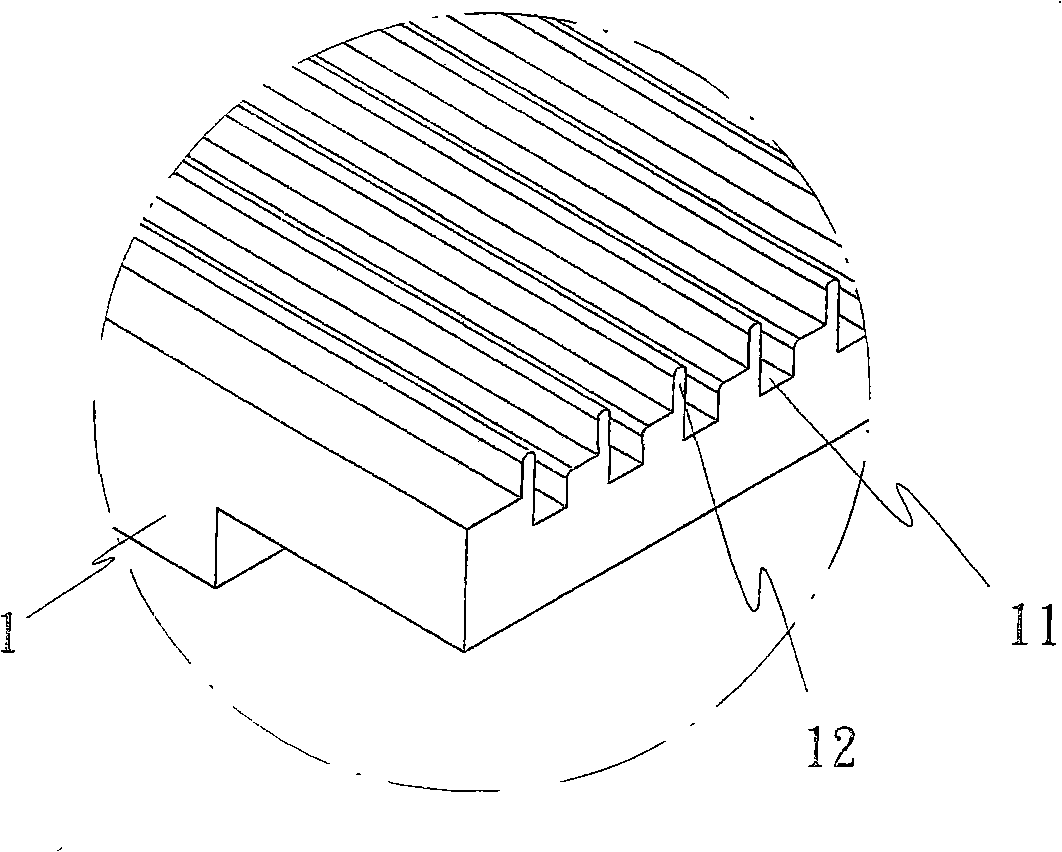
[0036] The seat body 1 is provided with a plurality of adjacent grooves 11 on the surface, and one side of the wall of each groove 11 is provided with a first protrusion 12 extending upwards (such as image 3 );

[0037] The plurality of cooling fins 2 all form a bent part 21 at the bottom of the fin body, so that the bent part 21 can be matched with the groove 11 implanted in the seat body 1;

[0038] Utilize above-mentioned seat body 1 and plural cooling fins 2, after each cooling fin 2 all matches and implants the groove 11 of seat body 1, can cooperate with the pressing down of stamping die 3 (such as Figure 4 ) to force the first protruding portion 12 to produce downward deformati...


PUM


Abstract

The invention relates to a radiator, comprising a plurality of radiating fins and a seat body. The surface of the seat body is provided with a plurality of adjacent grooves; one side of the groove wall of each groove is respectively provided with a first convex part or the other side of the groove wall is also additionally provided with a second convex part; the bottom end of each radiating fin isprovided with a bending part; when the radiating fins are matched and implanted into the grooves of the seat body, the stamping die is pressed to force the first convex part to be deformed and further tightly butted against the bending part of the radiating fin, thus forming good pressing combination, leading the radiating fins to be capable of completely being inserted to the bottom and firmly positioned respectively, further ensuring equal height of each radiating fin and having no deformation or unstable combination.

Description

technical field [0001] The invention relates to a heat sink design, in particular to an improved heat sink in which the heat sink and seat system are combined by pressing down. Background technique [0002] In addition to welding, conventional heat sinks also have a plurality of grooves on the surface of the base body for matching and inserting heat sinks, such as the design of the U.S. Patent No. 6,571,859; or further in the aforementioned Stamping is applied to the upper end surface of the groove, so that the end surface of the groove is deformed under pressure, and the two side walls of the groove provide lateral deformation pressure, so the insertion root of the heat sink can be pushed at the same time, resulting in a squeezing and clamping effect , such as U.S. Patent No. 5,014,776, Taiwan Patent No. I234,255, or Patent No. 572,577, etc. [0003] The above-mentioned conventional radiators, if the combination is completed by welding, must use manufacturing processes or ...

Claims


Application Information

Patent Timeline
Patent Type & Authority Patents(China)
IPC IPC(8): F28D15/02F28F3/08F28F9/26
CPCF28F3/02F28D15/0275
Inventor 黄崇贤
Owner HUIZHOU HANXU HARDWARE PLASTIC TECH CO LTD
Why Eureka
Try Eureka