Current protection device of preamplifier

A preamplifier, current protection technology, applied in emergency protection circuit devices, emergency protection circuit devices for limiting overcurrent/overvoltage, circuit devices, etc., can solve the fuse, and some still work at 1.4A, mind blowing problems

Inactive Publication Date: 2009-10-07
PANDA ELECTRONICS GROUP +2
View PDF0 Cites 5 Cited by
  • Summary
  • Abstract
  • Description
  • Claims
  • Application Information

AI Technical Summary

Problems solved by technology

[0003] A fuse is usually used to protect the equipment. For example, a 1A fuse is connected in series with the positive power port of the preamplifier. The reason is very simple. When the load (preamplifier operating current) exceeds 1A, the fuse can be blown. The above situation occurs. It is not wrong to connect the fuse because of a local short circuit in a certain component of the preamplifier unit, but the problem is that the fuses of different manufacturers with the same specifications have different fusing currents. Still working at 1.4A, mind-wrenching

Method used


Image

  • Current protection device of preamplifier

Examples


Embodiment Construction

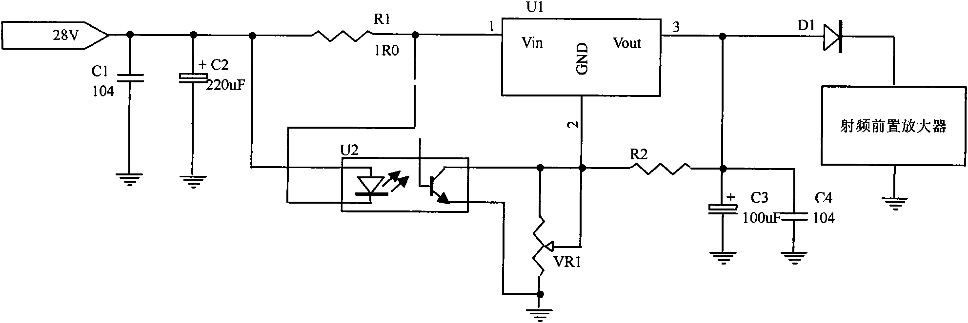
[0008] figure 1 It is a preamplifier current protection device. The power supply is connected in series with a precision resistor to the three-terminal voltage regulator, the output of the three-terminal voltage regulator is connected to the preamplifier, the precision resistor is connected in parallel with an optocoupler, and the triode output of the optocoupler is connected in parallel with the adjustable resistor. The working voltage of the preamplifier is 24V, the current is around 1A, the input voltage at the upper left end is +28V, C1 and C2 are input voltage filter capacitors, and R1 in the figure is a power-type current-limiting resistor, usually a wire-wound resistor. It not only provides current to the voltage stabilizing circuit, but also provides sampling voltage to the optocoupler device. The precision of resistor R1 is required to be 1%, the power is about 2W, and the resistance value is 1Ω. When the preamplifier works normally, its working current will not When...


PUM


Abstract

A current protection device of a preamplifier consists of a precision resistance, a three terminal regulator, the preamplifier, an optical coupler, a centretap resistance, a capacitor and a power supply; wherein the power supply is connected in series with the precision resistance to the three terminal regulator; the output of the three terminal regulator is connected with the preamplifier; the precision resistance is connected with the optical coupler in parallel; the triode output of the optical coupler is connected with the centratap ressitance and the capacitor grounding in parallel; wherein the tap of the centretap resistance is connected with the grounding terminal of the three terminal regulator. The current protection device has the beneficial effects that the protection device in the circuit can reduce the power supply voltage automatically and in time; the voltage reduction is more obvious when the short circuit is more serious; the current protection circuit added in the preamplifier brings more convenience for the practical operation doubtlessly and saves the procedure of replacing the fuse.

Description

1. Technical field [0001] The invention relates to a protection device for electronic communication equipment, especially a current protection device for a preamplifier. 2. Background technology [0002] Most of the existing electronic products are equipped with such a device as a fuse. For example, household appliances such as color TVs and washing machines in civilian products are without exception. The fuse is a basic protection measure for AC power supply equipment, and it is also very effective. One of the measures, the function of the fuse is very simple, that is, when the working current of a certain path in the equipment exceeds the rated current value, the fuse will blow immediately to protect the safety of the equipment. It is unimaginable to have a high-power device without a fuse. Once the device is short-circuited, the high current may cause the wire sheath to burn due to the heat generated by the core wire and cause a fire. Similar problems will also occur if t...

Claims


Application Information

Patent Timeline
Patent Type & Authority Applications(China)
IPC IPC(8): H02H9/04
Inventor 朱自付
Owner PANDA ELECTRONICS GROUP
Why Eureka
Try Eureka