Valve side linearly coupled double-bridge shaft-type pressed rectifying device

A rectifier and straight row technology, which is applied to output power conversion devices, bus/circuit layout, electrical components, etc., can solve the problems of difficult installation, low safety, and reduced current sharing coefficient, and achieve improved maintenance safety, The effect of simple busbar layout and improved safety

Inactive Publication Date: 2009-10-07
XIAN ZHONGDIAN TRANSFORMER RECTIFIER FACTORY
View PDF0 Cites 4 Cited by
  • Summary
  • Abstract
  • Description
  • Claims
  • Application Information

AI Technical Summary

Problems solved by technology

[0003] 1. Difficulty in installation: This structure is very easy to cause the hole distance between the rectifier cabinet and the transformer to be difficult to align or the installation is difficult due to a series of reasons such as curvature errors.
[0004] 2. Decrease in flow sharing degree: Due to the arrangement of components, the impedance of each branch circuit component is different, resulting in a decrease in the flow sharing coefficient
[0005] 3. Large loss: This kind of technical structure is complicated, and the connection between the rectifier device and the transformer must be bent, which increases the AC reactance of the bu

Method used


Image

  • Valve side linearly coupled double-bridge shaft-type pressed rectifying device
  • Valve side linearly coupled double-bridge shaft-type pressed rectifying device
  • Valve side linearly coupled double-bridge shaft-type pressed rectifying device

Examples


Embodiment Construction

[0030] The present invention will be described in detail below in conjunction with the accompanying drawings.

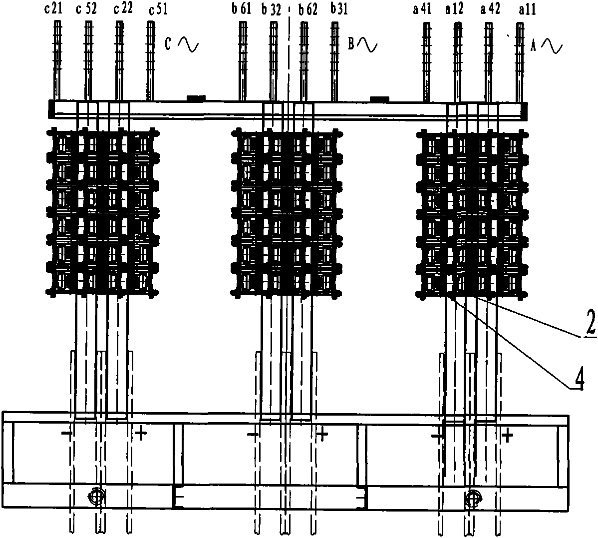
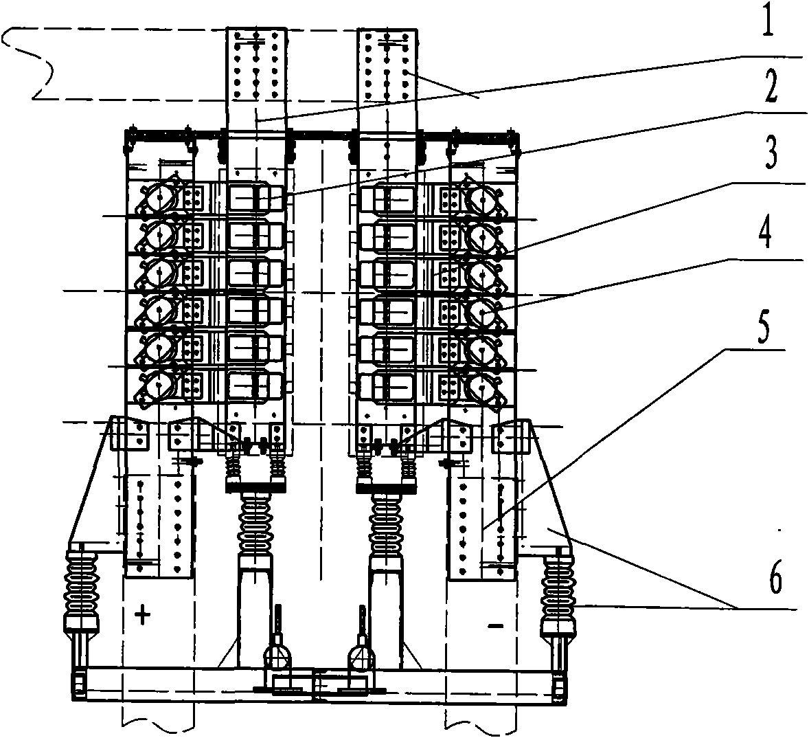
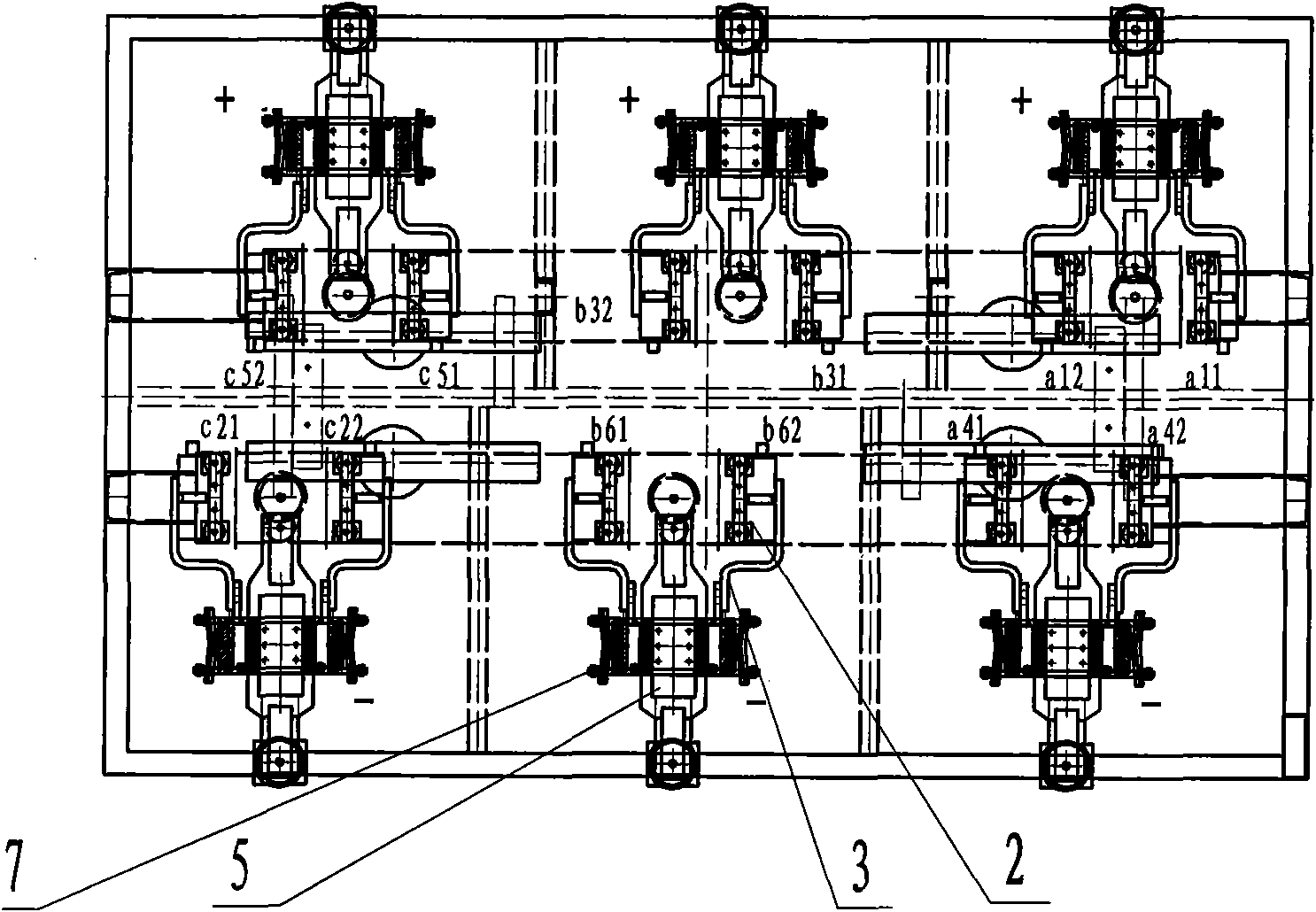
[0031] see figure 1 , figure 2 , image 3 , the present invention consists of a fast-melting busbar double-hole water-cooled bus 1 (three-phase bridge AC incoming line), a fast fuse 2, a connecting bus 3, a rectifier element 4, a component bridge arm porous water-cooled bus 5 (DC outgoing line), and a support member 6 In terms of configuration, the above-mentioned rectifying element 4 is installed symmetrically on the busbar of the bridge arm, that is, the components are installed symmetrically on both sides with the porous water-cooled busbar 5 of the bridge arm as the axis. The impedance of each branch circuit element is the same, and the force is the same, so the problem of the decrease of the current sharing coefficient caused by the arrangement of the elements is avoided to a certain extent. The problem of current equalization can be solved structurally, and...


PUM

PropertyMeasurementUnit
Spacingaaaaaaaaaa

Abstract

The invention relates to the technical filed of power electronic equipment. The structure of the current cophase anti-parallel connection rectifying cabinet is as follows: a rectifying device is coupled with a transformer through a bended bus on the side of an alternating current (AC) valve; and the structure has the disadvantages of difficult installation, low flow equalization degree, large consumption, easy short circuit, low safety, complicated cooling water channel inside the rectifying device, and severe electric corrosion. The rectifying device comprises a quick-melt busbar double-hole water-cooling bus, an element bridge-arm multi-aperture water-cooling bus, a rectifying element, a connection bus and a quick fuse; and an AC bus of the rectifying device structurally corresponds to the connection bus on the side of a cophase anti-parallel connection rectiformer and the two buses are linearly butted. The rectifying device has the advantages of convenient installation, improvement for flow equalization degree, low consumption, short circuit avoidance, higher safety, simplified cooling water channel inside the rectifying device, and little electric corrosion.

Description

technical field [0001] The invention relates to the technical field of power electronic equipment, in particular to the direct connection with the busbar on the valve side of a rectifier transformer and the axial press-fitting of components, and is a double-bridge shaft press-fit rectifier in line with the valve side. Background technique [0002] The structure of the current "in-phase and anti-parallel rectifier cabinet" is: the rectifier device and the transformer need to be connected by the bus bar on the side of the AC valve after bending. It has the following disadvantages: [0003] 1. Difficulty in installation: This structure is very easy to cause the hole distance between the rectifier cabinet and the transformer to be difficult to align or the installation is difficult due to a series of reasons such as bending errors. [0004] 2. Decrease in flow sharing degree: due to the arrangement of components, the impedance of each branch circuit component is different, resu...

Claims


Application Information

Patent Timeline
IPC IPC(8): H02M1/00H02B1/20
Inventor 贾继业
Owner XIAN ZHONGDIAN TRANSFORMER RECTIFIER FACTORY
Why Eureka
Try Eureka