Method for controlling transmission of sink nodes in wireless sensor network

A wireless sensor and aggregation node technology, applied in wireless sensor network protocol design, wireless network field, can solve problems such as low performance, large bandwidth delay product, link bandwidth asymmetry, etc., to improve throughput, improve stability, The effect of less fluctuation in the send window

Inactive Publication Date: 2009-10-14
SOUTHEAST UNIV
0 Cites 28 Cited by

AI-Extracted Technical Summary

Problems solved by technology

However, the wireless network environment where the aggregation node is located has the characteristics of high bit error rate (Bit Error Rate, BER), link bandwidth asymmetry, and...

Abstract

The invention provides a method for controlling the transmission of sink nodes in a wireless sensor network. The method comprises the following steps: firstly, averaging the confirmed time intervals of ack packets, then, measuring the available bandwidth and further filtering the acquired available bandwidth with a filter to eliminate errors, thereby acquiring the more accurate value of the available bandwidth; dividing the congestion avoidance stage into two linear-growth stages by measuring the buffer length of the bottleneck link and combining the estimated value of the available bandwidth, particularly, increasing the sending rate of data packets towards the maximal network capacity rapidly and then reducing the rate of reaching the maximal network capacity, so that the sending process can remain stable at a higher sending rate for a long time; and distinguishing congestion packet loss from wireless error code packet loss by the buffer length of the bottleneck link when the packet loss occurs, and rapidly restoring the sending window to the normal size in the wireless sensor network environment with a higher bit error rate, so that the ssthresh (slow start threshold) and the sending window can be adjusted to a proper value according to the network status, and the stability and the throughput rate of the transmission can be effectively improved.

Application Domain

Technology Topic

Real-time computingLinear growth +10

Image

  • Method for controlling transmission of sink nodes in wireless sensor network
  • Method for controlling transmission of sink nodes in wireless sensor network
  • Method for controlling transmission of sink nodes in wireless sensor network

Examples

  • Experimental program(1)

Example Embodiment

[0019] The technical solution of the present invention will be further described below in conjunction with the drawings and specific implementation examples.
[0020] The method for measuring the available bandwidth based on the arrival interval of ACK packets in the present invention is to measure the time interval of the arrival of the acknowledgement packet and average the time interval to calculate the available bandwidth, and then use a filter to filter the measured available bandwidth to eliminate errors. This results in a more accurate measurement of the available bandwidth. The specific method is as follows: Assuming that the size of the data packets are all P, after passing through the bottleneck link, the data packets form a certain interval, and the time interval formed by ACK packets after reaching the destination node is Δt 1 , Δt 2 , Δt 3..., Δt n-1 , Δt n , The available bandwidth measurement value is:
[0021] B = Σ i = 1 n P i / Σ i = 1 n Δt i = n × P / Σ i = 1 n Δt i = P / ( Σ i = 1 n Δt i / n ) - - - ( 1 )
[0022] It can be seen from formula (1) that the measured bandwidth is the data packet size divided by the average interval time.
[0023] The method of averaging the time intervals is that the sending node records the arrival time of each ACK confirmation packet for a period of time, calculates the time interval between ACK packets and the number of time intervals, and then calculates the mathematical expectation for these time intervals.
[0024] After obtaining the current bandwidth measurement value, a discrete-time filter is used to eliminate the measurement error, assuming that at time t k When the measured bandwidth value is b k , The bandwidth value obtained by filter sampling is According to the bandwidth measurement method in the reference "TCP westwood: congestion window control using bandwidth estimation" (Gerla M, Sanadidi M Y, Wang R, IEEE Globecom, San Antonio, pp. 1698-1702, 2001):
[0025] b ^ k = α k b ^ k - 1 + ( 1 - α k ) ( b k + b k - 1 2 ) = 2 τ - Δt k 2 τ + Δt k × b ^ k - 1 + ( 1 - 2 τ - Δt k 2 τ + Δt k ) × ( b k + b k - 1 2 ) - - - ( 2 )
[0026] Where α k Is the time-varying exponential filter coefficient, 1/τ is the switching cut-off frequency of the filter, b k-1 with They are the last bandwidth measurement value and the last bandwidth value obtained through filter sampling.
[0027] The estimated value of the bottleneck link length adopts and refers to the document "TCP Vegas: end to end congestion avoidance on a global internet" (Brakmo LS, Perterson L L., IEEE Journal on Selected Areas in Communications, 13(8): 1465-1480, 1995) Similar method, suppose the current data packet sending rate is cur_rate=cwnd/RTT, and the base sending rate is base_rate=cwnd/BaseRTT, where BaseRTT is the measured minimum data packet round-trip time value, and RTT is the filter elimination The round-trip time value of the data packet after interference, cwnd is the current congestion window size, and the bottleneck link buffer length is L, then the bottleneck link buffer length calculation method is L=cur_rate×(RTT-BaseRTT).
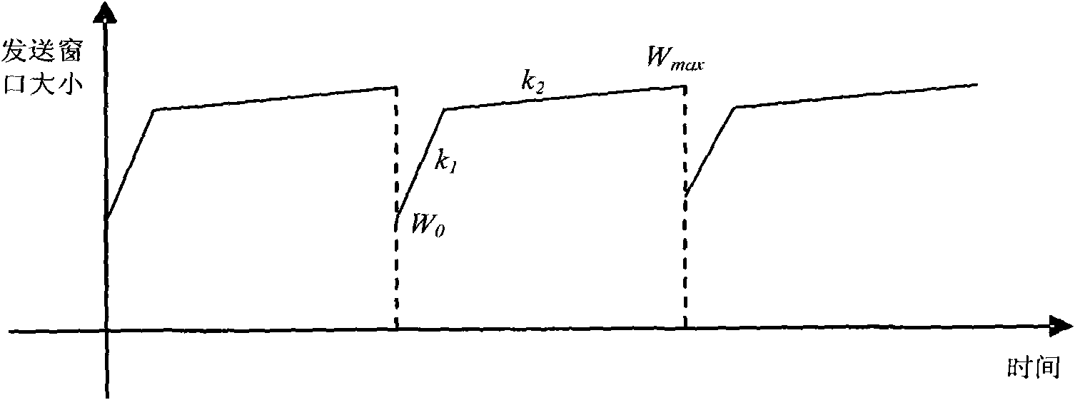
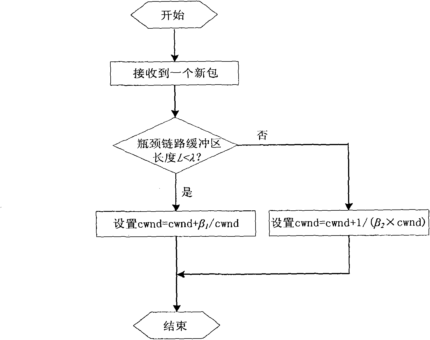
[0028] Congestion avoidance phase control adopts a piecewise linear growth sending window growth method, combined with the available bandwidth measurement value and the current bottleneck link buffer length measurement value, the congestion avoidance phase is divided into two linear growth phases, so that the data packet transmission rate is faster Increase to close to the maximum capacity of the network, and then slow down the speed to reach the maximum capacity of the network, so that the sending process will stabilize at a higher sending rate for a long time. figure 2 Schematic diagram of the segmented transmission window change in the congestion avoidance phase, image 3 For the flow chart of the transmission control method in the congestion avoidance phase, set the length of the measurement bottleneck link buffer as L and set the threshold λ, if L 1/cwnd, corresponding to figure 2 The middle slope is k 1 Growth process. If L>λ, it means that the network is close to congestion at this time, and the window increase value needs to be slowed down as much as possible to make the sending process stable for a long time close to the maximum network capacity. The sending window increase method is cwnd=cwncd+1/(β 2 ×cwnd), corresponding to figure 2 The middle slope is k 2 Growth process. Where β 1 And β 2 Is a regulatory factor, β 1 Used to control the growth rate of the sending window in the congestion avoidance phase, when β 1 When the congestion window is too large, the congestion window will grow too fast, which will easily cause congestion and packet loss to affect the transmission performance. Otherwise, the network capacity cannot be fully utilized; β 2 Affect the time that the sending process stays at the maximum capacity of the network. The size of the sending window in each congestion avoidance phase is at the minimum value W 0 And maximum W max Change between.
[0029] In a wireless sensor network with error codes, by distinguishing the causes of congestion and error packet loss in the wireless environment and taking reasonable measures, when packet loss occurs, it can distinguish between congested packet loss or wireless error packet loss according to the length of the bottleneck link buffer. The congestion window size can be quickly restored in a wireless network environment with a high bit error rate, and the slow start threshold and the sending window can be adjusted to an appropriate value according to the network condition. Set the threshold δ. When receiving 3 duplicate ACK packets, if the length of the bottleneck link buffer L cur +RTT min )/2, when L>δ, it indicates that the current network tends to be congested. At this time, set the slow start threshold to ssthresh=bwe×RTT min , Many experiments show that the effect is better when the δ value is set to 5. The specific algorithm is as follows Figure 4 Shown. When the sending timer expires and the packet is lost, it can basically be judged that the amount of sent data exceeds the maximum capacity of the bottleneck link and causes network congestion. Therefore, the bandwidth value measured at this time is used as the basis for setting the slow start threshold, and the slow start threshold is set to ssthresh=bwe ×RTT min.

PUM

no PUM

Description & Claims & Application Information

We can also present the details of the Description, Claims and Application information to help users get a comprehensive understanding of the technical details of the patent, such as background art, summary of invention, brief description of drawings, description of embodiments, and other original content. On the other hand, users can also determine the specific scope of protection of the technology through the list of claims; as well as understand the changes in the life cycle of the technology with the presentation of the patent timeline. Login to view more.

Similar technology patents

Multi-unmanned aerial vehicle route planning method based on bee colony collaborative foraging algorithm

InactiveCN103471592AOvercoming initialization sensitivity issuesImprove stabilityConjoint controlsNavigational calculation instrumentsRoute planningDiscrete transformation
Owner:HARBIN ENG UNIV

Classification and recommendation of technical efficacy words

Why Eureka
Try Eureka