
Direct connection low-speed small-scale mixed-flow turbine applied in hydrodynamic energy-saving cooling tower

A technology of cooling towers and water turbines, applied in the direction of reaction engines, engine components, impact engines, etc., can solve the problems of high manufacturing and maintenance costs, high failure rate, small size, etc., to improve efficiency, reduce noise, reduce manufacturing and maintenance cost effects

Inactive Publication Date: 2009-10-21
NANJING XINGFEI COOLING EQUIP
View PDF0 Cites 14 Cited by
  • Summary
  • Abstract
  • Description
  • Claims
  • Application Information

AI Technical Summary

Problems solved by technology

[0005] The purpose of the present invention is to design a water turbine with high efficiency and small size that can be widely used in hydrodynamic energy-saving cooling towers for the problems of high noise, high failure rate, and high manufacturing and maintenance costs in the cooling tower water turbine with a reduction box. The direct-connected low-speed small Francis turbine, so that the cooling tower turbine completely bid farewell to the gear reducer

Method used


Image

  • Direct connection low-speed small-scale mixed-flow turbine applied in hydrodynamic energy-saving cooling tower
  • Direct connection low-speed small-scale mixed-flow turbine applied in hydrodynamic energy-saving cooling tower
  • Direct connection low-speed small-scale mixed-flow turbine applied in hydrodynamic energy-saving cooling tower

Examples


Embodiment Construction

[0028] The present invention will be further described below in conjunction with the accompanying drawings and embodiments.

[0029] Such as Figure 1-5 shown.

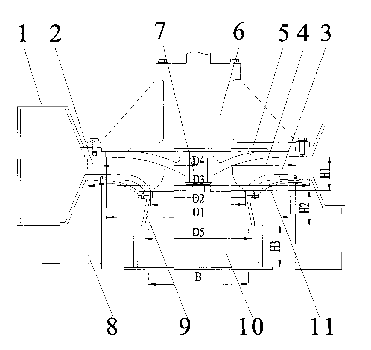
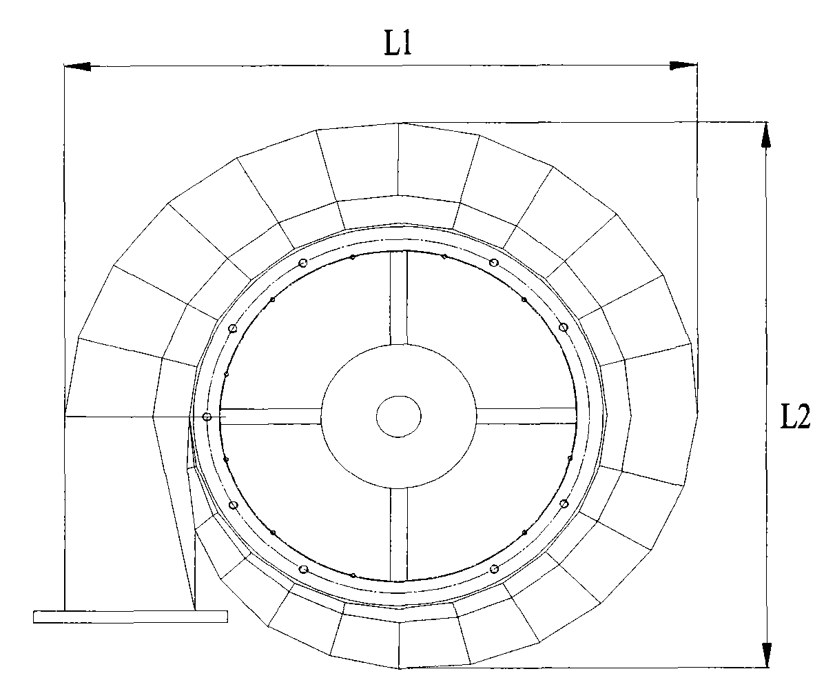
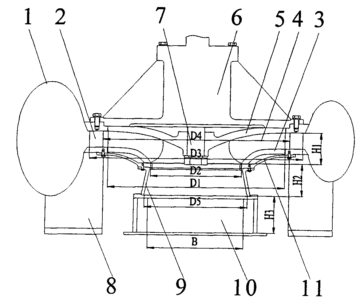
[0030] A direct-connected low-speed small Francis turbine applied to a hydrodynamic energy-saving cooling tower, which includes an elliptical water inlet cross section ( image 3 ) or trapezoidal ( figure 1 ) metal volute 1, a seat ring 2 with a single row of annular guide vanes, a low-speed Francis turbine runner 12 composed of a lower ring 3, curved blades 4, and an upper crown 5, and a straight cone outlet pipe 9 And a side outlet water tank 10, the seat ring 2 is installed on the inner side of the volute 1, the volute 1 is supported on the pier 8, and the bottom of the runner 12 is equipped with a manifold 11, such as figure 1 As shown, the water inlet between the guide vanes in the seat ring 2 communicates with the water outlet channel of the volute 1, the water inlet of the volute 1 communicates with the wate...


PUM


Abstract

A direct connection low-speed small-scale mixed-flow turbine applied in a hydrodynamic energy-saving cooling tower, comprising a volute (1) for flooding water, a seating ring (2) provided with single row of guide vanes in a circular way, a runner (12), a straight-taper type water outlet pipe (9) and a side water outlet tank (10); wherein the seating ring (2) is arranged at the inner side of the volute (1), a water outlet port formed by guide vanes of the seating ring (2) is communicated with a water inlet port formed by curved vanes (4), a water outlet port formed by the curved vanes (4) is communicated with a water inlet port of the straight-taper type water outlet pipe (9), and an water outlet port of the straight-taper type water outlet pipe (9) is communicated with a water inlet port of the side water outlet tank (10). The turbine is characterized in that a shaft block (6) is arranged on the runner (12) and is internally provided with a shaft (7) which is directly mounted with a cooling fan blade; the value of the unit speed n11=nD1 / square root of H is 28-42, wherein n is the rated speed of the cooling fan blade, D1 is the diameter of a water inlet port of the runner (12), H is the hydraulic pressure for entering a tower. The invention has the advantages of small size, high efficiency and low noise.

Description

technical field [0001] The invention relates to a cooling tower, especially a water turbine for driving the cooling fan of the cooling tower, specifically, a water turbine without a reduction box, which can be realized by rationally designing the dimensions of each part, especially the key parameters of the water inlet seat ring and the runner. The output speed of the water turbine is the rated value of the speed of the fan, so that the reduction box used by the traditional reaction water turbine is omitted, and the direct-connected low-speed small Francis water turbine applied to the hydrodynamic energy-saving cooling tower. Background technique [0002] As we all know, air-conditioning cooling towers, especially industrial air-conditioning cooling towers, have enough surplus energy in the cooling circulating water in the design. In order to achieve the purpose of energy saving, this part of surplus energy is recovered by using water turbines and converted into rotating mech...

Claims


Application Information

Patent Timeline
Patent Type & Authority Applications(China)
IPC IPC(8): F03B13/00F03B1/00
CPCY02E10/223Y02E10/28F03B13/00F03B3/02Y02E10/20Y02E10/30F03B17/06
Inventor 顾星康
Owner NANJING XINGFEI COOLING EQUIP
Learn More