Straight-line reciprocating piston type compressor

A linear reciprocating, piston-type technology, applied in the field of compressors, can solve the problems of increased power consumption, poor sealing performance, and increased overall size of the compressor, and achieve the effects of improved work efficiency, small vibration, and small friction

Active Publication Date: 2009-10-21
ZHEJIANG HONGYOU AIR COMPRESSOR MFG
View PDF2 Cites 10 Cited by
  • Summary
  • Abstract
  • Description
  • Claims
  • Application Information

AI Technical Summary

Problems solved by technology

[0002] At present, most compressors use a motor to drive the crankshaft of the compressor to rotate, and then the crankshaft drives the connecting rod to push the piston of the compressor, or the crankshaft drives the swinging piston of the connecting rod and the piston to compress gas or liquid to do work. Due to the connection between the crankshaft and the connecting rod of the compressor of the structure, the crankshaft is directly inserted into the connecting hole of the connecting rod, and the crankshaft drives the connecting rod to swing and reciprocate. Increase the power consumption of the compressor and increase the wear and tear
Piston swing causes poor sealing performance and reduced compression efficiency. If the swing range is to be reduced, the length of the connecting rod must be lengthened, which will inevitably increase the overall size

Method used


Image

  • Straight-line reciprocating piston type compressor
  • Straight-line reciprocating piston type compressor
  • Straight-line reciprocating piston type compressor

Examples


Embodiment 1

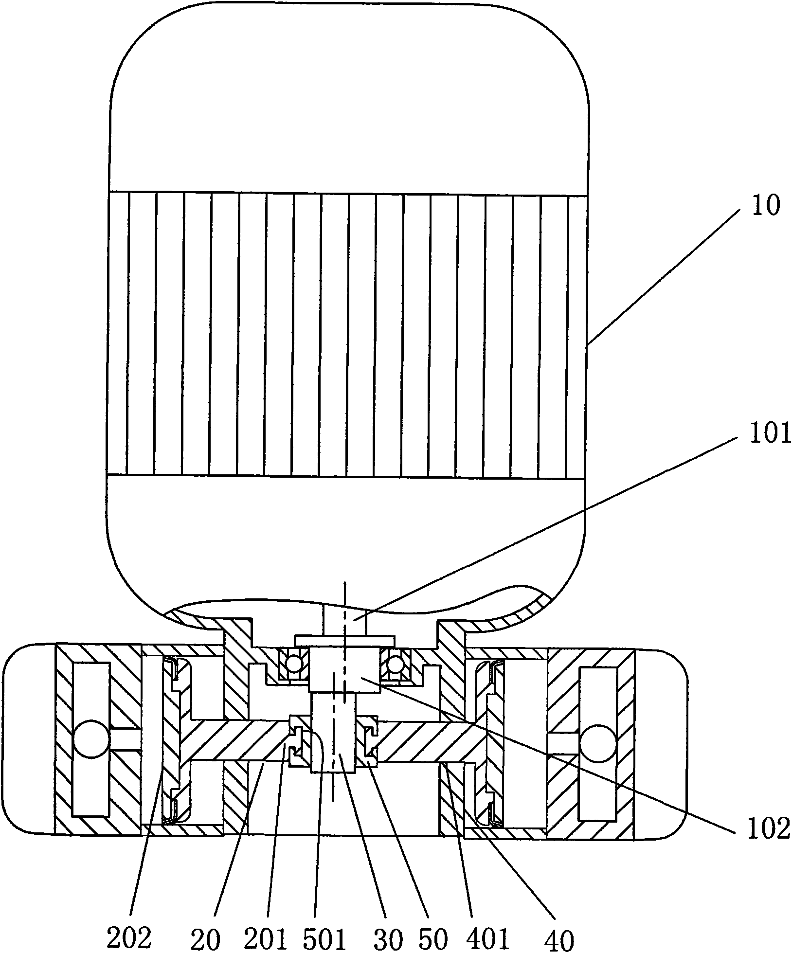
[0046] Example 1, see Figure 1-2 :

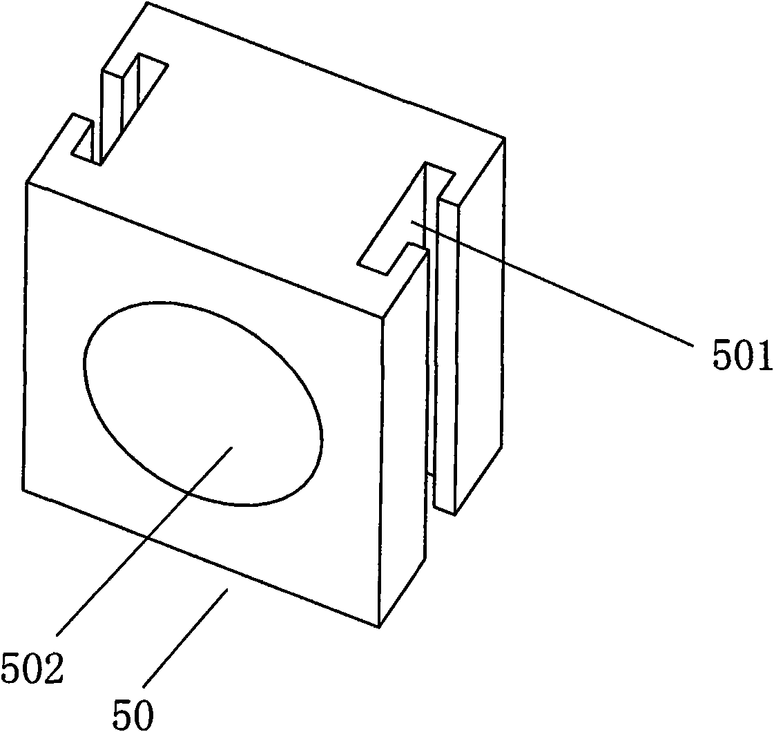
[0047] The structure of the linear reciprocating piston compressor includes a motor 10, a crankcase 40, a crankshaft 30, a piston rod 201, a cylinder, and an intake and exhaust device. The main shaft 102 of the motor 10 is directly connected to the crankshaft 30, and one end of the piston rod 20 is provided with a The piston part 202 is provided with a piston rod 20 with a force transmission part 201 at the other end, and the force transmission part 201 of the piston rod 20 is connected with the outer guide rail 501 of the slider 50, and the middle part of the slider 50 is provided with a bearing hole matched with the crankshaft 30 502, the crankshaft 30 is set in the bearing hole 502 of the slider 50, the above-mentioned crankcase 40 is provided with the motion guide structure 401 of the piston rod 20, the above-mentioned piston part 202, the piston rod 20 and the matching cylinder and the intake and exhaust There are two sets of devices...

Embodiment 2

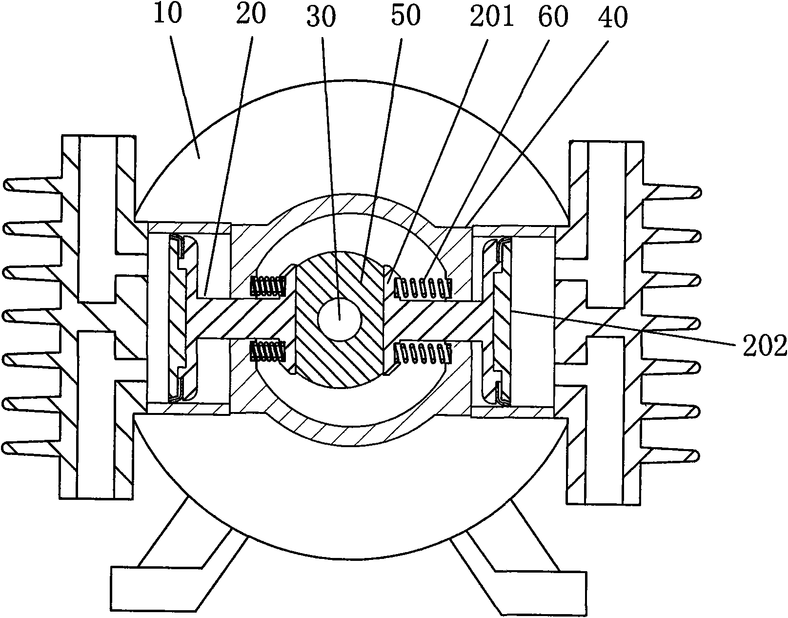
[0048] Example 2, see image 3 :

[0049] The structure of embodiment 2 is basically the same as that of embodiment 1, the difference being that a slide block 50 is set on the crankshaft 30, between the force transmission part 201 of the piston rod 20 and the crankcase 40 in the direction of movement of the piston rod 20 A spring 60 is arranged between them, and the spring 60 presses the slider 50 and the force transmission part 201 of the piston rod 20 so that the force transmission part 201 of the piston rod 20 and the slider 50 always keep zero-distance contact.

Embodiment 3

[0050] Embodiment 3: see Figure 4 and image 3 :

[0051] The structure of embodiment 3 is basically the same as that of embodiment 2, the difference is that a number of friction-reducing needle rollers 70 are arranged between the slider 50 and the force transmission part 201 of the piston rod 20, and the needle rollers 70 can reduce friction. Frictional force between the slider 50 and the force transmission part 201 .


PUM


Abstract

The invention discloses a structure of a straight-line reciprocating piston type compressor. The connecting mode between a crankshaft and a power transmission part of a piston rod is as follows: the crankshaft is sleeved with a sliding block; the sliding block and the power transmission part are pressed or tightened by a tension spring, a spring reed or a spring; or based on the connection, rolling bodies of rolling needles, or rolling balls and the like, or other sliding bodies with low friction coefficient are arranged between the sliding block and the power transmission part; or the crankshaft is sleeved with a bearing; the bearing and the power transmission part are pressed or tightened by a tension spring, a spring reed or a spring; or the crankshaft is sleeved with the sliding block;the contact surface of the sliding block and the power transmission part is provided with a guide rail; and the power transmission part is arranged in the guide rail and can move in the guide rail ina reciprocating way. The structure of the straight-line reciprocating piston type compressor has the following advantages that: (1) the zero gap transmission is realized between the crankshaft and the piston rod, the equipment has little friction force, little vibration, low noise and accurate and reliable transmission; (2) a plurality of cylinders can be arranged for exhausting when the piston type compressor rotates by one circle, thus greatly improving the work efficiency of the motor and being suitable for being applied in the transmission structure of the piston type compressor.

Description

Technical field: [0001] The invention belongs to the technical field of compressors, in particular to a linear reciprocating piston type compression mechanism. Background technique: [0002] At present, most compressors use a motor to drive the crankshaft of the compressor to rotate, and then the crankshaft drives the connecting rod to push the piston of the compressor, or the crankshaft drives the swinging piston of the connecting rod and the piston to compress gas or liquid to do work. Due to the connection between the crankshaft and the connecting rod of the compressor, the crankshaft is directly inserted into the connecting hole of the connecting rod, and the crankshaft drives the connecting rod to swing and reciprocate. Increase the power consumption of the compressor and increase the wear and tear. Piston swing causes poor sealing performance and reduced compression efficiency. If the swing range is to be reduced, the length of the connecting rod must be lengthened, w...

Claims


Application Information

Patent Timeline
Patent Type & Authority Applications(China)
IPC IPC(8): F04B27/02
Inventor 陈君立阮勤江王治超孙世杰
Owner ZHEJIANG HONGYOU AIR COMPRESSOR MFG
Why Eureka
Try Eureka