Combined photoacoustic and ultrasound imaging system

An imaging system, photoacoustic image technology, applied in ultrasonic/acoustic/infrasonic Permian technology, ultrasonic/sonic/infrasonic image/data processing, radio wave measurement system, etc.

Active Publication Date: 2009-10-21
KONINKLIJKE PHILIPS ELECTRONICS NV
View PDF0 Cites 32 Cited by
  • Summary
  • Abstract
  • Description
  • Claims
  • Application Information

AI Technical Summary

Problems solved by technology

The photoacoustic image can be corrected for motion using the motion estimator data by the image combiner

Method used


Image

  • Combined photoacoustic and ultrasound imaging system
  • Combined photoacoustic and ultrasound imaging system
  • Combined photoacoustic and ultrasound imaging system

Examples


Embodiment Construction

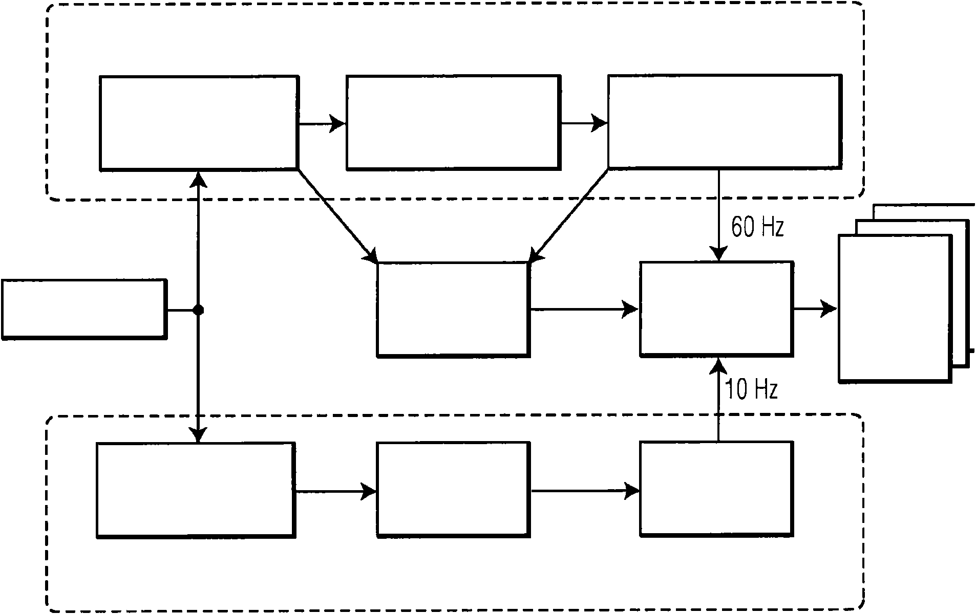
[0021]The present disclosure relates to systems and methods for combining photoacoustic (PA) and ultrasound images. Such systems and methods can generate images using PA or ultrasound image generating devices. The acquisition of these images can be interlaced so that they appear to be acquired simultaneously from the user's point of view. These two image modalities rely on different contrast mechanisms, and they will thus generate different information. For example, ultrasound images show boundaries between different tissues with different acoustic impedances, while PA images show absorption of laser energy at the associated light wavelength used.

[0022] A system according to the present disclosure is used to simultaneously display PA and ultrasound images of the same subject. An exemplary embodiment of a system associated with the present disclosure includes an image combiner that performs spatial and temporal interpolation of the two images (PA and ultrasound) prior to g...


PUM


Abstract

The present disclosure provides for a system that is adapted to simultaneously display photoacoustic and ultrasound images of the same object. An image combiner can perform spatial and temporal interpolation of the two images before generating a combined image. The combined image is then displayed on a display such as an LCD or CRT. The system is able to use motion estimates obtained from the ultrasound data to enhance the photoacoustic image thereby increasing its apparent frame rate, registering consecutive frames in order to reduce artifacts. The system is capable of generating combined ultrasound and photoacoustic images which are registered spatially and temporally.

Description

technical field [0001] The present disclosure relates to systems and methods related to photoacoustic and ultrasound imaging. Background technique [0002] Photoacoustic (PA) tomography is an emerging medical imaging modality. (See, e.g., "The Twente Photoacoustic Mammoscope: System Overview and Performance," by S. Manohar, A. Kharine, J.C.G. van Hespen, W. Steenbergen, and T.G. van Leeuwen, "Physics in Medicine and Biology, Vol. 50, No. 11, No. 2543- 2557, June 2005; M. Xu and L. Wang, "Universal back-projection algorithm for photoacoustic computer tomography," Physical Review E, Vol. 71, No. 1, p. 16706, 2005). Typically, short laser pulses are directed at an object of interest (eg, human or animal tissue). Laser energy is absorbed by structures within the object, causing rapid temperature rise and thermal expansion. This thermal expansion causes ultrasonic waves to propagate through the object, where they are received by ultrasonic transducers located on the object's s...

Claims


Application Information

Patent Timeline
Patent Type & Authority Applications(China)
IPC IPC(8): A61B8/14G01N21/17A61B5/00A61B8/08G01S7/52
CPCA61B5/7207A61B8/5276A61B5/0059A61B8/08G01S15/899G01N21/1702A61B8/488G01S7/52074A61B5/0095A61B8/5238A61B8/4416A61B8/14A61B5/0035G01N21/17G01S7/52A61B8/5261
Inventor M·伯彻
Owner KONINKLIJKE PHILIPS ELECTRONICS NV
Why Eureka
Try Eureka