Pneumatic tire for two-wheeled vehicle

A technology for pneumatic tires and two-wheeled vehicles, which is applied to the reinforcement layer of pneumatic tires, motorcycle tires, tire parts, etc.

Inactive Publication Date: 2009-10-21
BRIDGESTONE CORP
View PDF5 Cites 8 Cited by
  • Summary
  • Abstract
  • Description
  • Claims
  • Application Information

AI Technical Summary

Problems solved by technology

[0002] In high-performance pneumatic tires for two-wheeled vehicles, since the rotation speed of the tire is high, the influence of centrifugal force is large, and the tread portion of the tire may expand outward in the radial direction of the tire, thereby impairing the steering stability performance.

Method used


Image

  • Pneumatic tire for two-wheeled vehicle
  • Pneumatic tire for two-wheeled vehicle
  • Pneumatic tire for two-wheeled vehicle

Examples


Embodiment 1

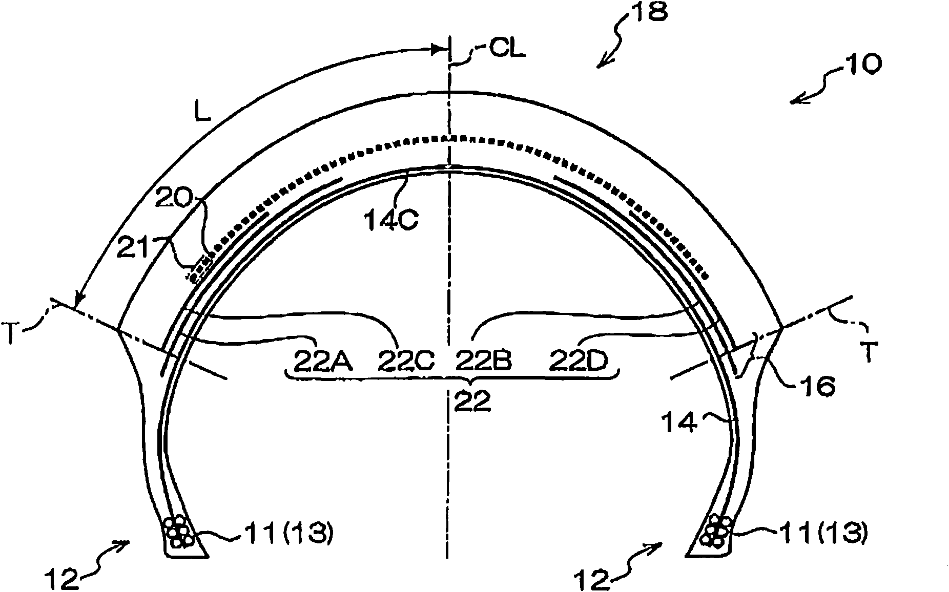
[0089] Example 1 is as figure 1 In the pneumatic tire for motorcycles constructed as shown, the width of the spiral belt layer 20 is 0.75 times the entire tread width 2L, which is 180 mm (the width on one side from the tire equator plane is 90 mm). The spiral belt layer 20 is formed by spirally winding steel cords obtained by twisting steel single wires with a diameter of 0.18 mm in a 1×3 pattern at a weft density interval of 60 cords / 50 mm.

[0090] In addition, two pairs of cross belt layers 22A to D (cross belt layers 22A and 22C are a pair and cross belt layers 22B and 22D are a pair) exist in the inner side of the spiral belt layer 20 . The width of the first intersecting belt layers 22A and 22B is 80 mm, and the outer end in the tire width direction protrudes 5 mm from the tread end T toward the tire outer side. The width of the second intersecting belt layers 22C and 22D is 50 mm, and the outer end in the tire width direction is at the same position as the tread end T...

Embodiment 2

[0093] Embodiment 2 is in embodiment 1 (with reference to figure 1 ) on the outer side of the spiral belt layer 20 in the radial direction, a reinforcing belt layer (the same as the reinforcing belt layer 34 used in Example 3 described later) is added with an angle of 90 degrees relative to the tire circumferential direction. structure. The width of the additional reinforcing belt layer is 240mm, and the material of the belt layer is aramid. The material of the reinforcing belt layer is the same as that of the cross belt layers 82I and 82E of the conventional example, and the weft density and cord diameter are also the same, but the cord angle is 90 degrees, which is different from the conventional example.

Embodiment 3

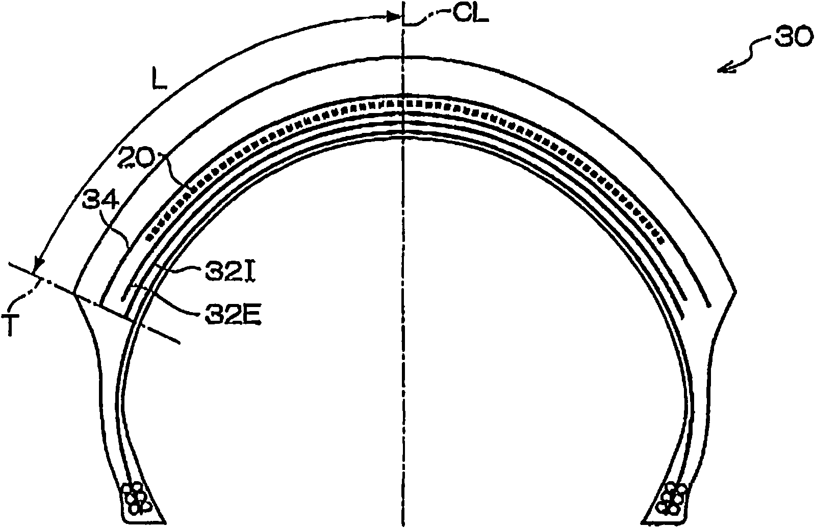
[0095] Example 3 is as figure 2 A pneumatic tire 30 for a two-wheeled vehicle configured as shown. Example 3 has the spiral belt layer 20 and the same cross belt layers 32I and 32E as the conventional example. That is, the first intersecting belt layer 32I has a width of 240 mm, and the second intersecting belt layer 32E has a width of 230 mm, and the cord angles thereof are crossed at 65 degrees with respect to the tire circumferential direction. The width of the spiral belt layer 20 is 180 mm as in other examples, which is different from the width of the spiral belt layer 80 employed in the conventional example. In addition, on the outer side of the spiral belt layer 20 in the radial direction, there is a reinforcing belt layer 34 having a cord angle of 90 degrees as in Example 2. As shown in FIG. The width of the reinforcing belt layer 34 is 240 mm as in Example 2, and the cord material constituting the reinforcing belt layer 34 is aramid.


PUM


Abstract

A pneumatic tire for a two-wheeled vehicle, having further increased driving stability, particularly in turning. The pneumatic tire (10) for a two-wheeled vehicle has a belt layer (16) and a tread section (18) that are sequentially arranged on the outer side, in the radial direction of the tire, of a crown section (14C) of a carcass (14). On the belt layer (16) is placed a spiral belt layer (20) formed by spirally winding a band-like rubber-coated cord layer so as to form a cord angle in the range of 0 to 5 degrees relative to the circumferential direction of the tire. With L the tread surface distance from the tire center CL to a tread end T, the spiral belt layer (20) is present only in the range of 0.65L to 0.85L from the tire center CL, and intersecting belt layers (22A-22D) are arranged in the range from an end in the lateral direction of the spiral belt layer (20) to the tread end T. The intersecting belt layers (22A-22D) include organic fiber cords intersecting with each other and having a cord angle of not less than 30 degrees and less then 75 degrees relative to the circumferential direction of the tire.

Description

technical field [0001] The present invention relates to a pneumatic tire for two-wheeled vehicles with improved handling stability at high speeds. Pneumatic tires for two-wheeled vehicles that provide traction performance when cornering. Background technique [0002] In high-performance pneumatic tires for two-wheeled vehicles, since the rotation speed of the tire is high, the influence of centrifugal force is large, and the tread portion of the tire may expand outward in the tire radial direction, thereby impairing the steering stability performance. In order to prevent this, a tire structure has been developed in which organic fibers and steel wire reinforcing members (coil members) are wound in layers on the tread portion of the tire substantially parallel to the equatorial plane of the tire. Nylon fiber, aramid (aramid, Kevlar), steel wire, etc. are used as the reinforcement member wound helically along the equatorial plane of the tire. Among them, aramid (aramid, Kevl...

Claims


Application Information

Patent Timeline
Patent Type & Authority Applications(China)
IPC IPC(8): B60C9/18B60C13/00B60C9/22
CPCB60C2009/2041B60C9/2009B60C11/0332B60C15/0018B60C9/2204B60C2200/10B60C9/28
Inventor 石山诚
Owner BRIDGESTONE CORP
Why Eureka
Try Eureka