Wet paper conveyance belt
A technology for conveyor belts and wet paper webs, applied in the field of wet paper web conveyor belts, can solve problems such as uncertain dimensions of wet paper web conveyor belts, and achieve the effect of reducing the increase in weft size
- Summary
- Abstract
- Description
- Claims
- Application Information
AI Technical Summary
Problems solved by technology
Method used
Image
Examples
example 1
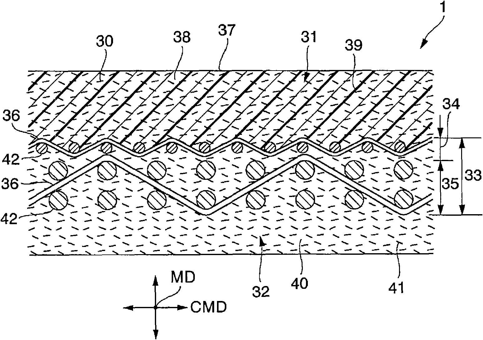
[0105] 1. Base fabric 33:
[0106] ·The upper fabric (first fabric 34) has a 1 / 1 plain weave structure (warp yarn 42 composed of nylon multifilament yarn and weft yarn 36 composed of PET single yarn), and has 200g / m 2 Unit weight.
[0107] The lower fabric (second fabric 35) has a warp double-layer structure (warp yarn 42 composed of nylon monofilament spun yarn and weft yarn 36 composed of nylon monofilament spun yarn), and has 400g / m 2 Unit weight.
[0108] 2. Cotton layer:
[0109] The batt layer 38 on the wet paper web side is formed of rayon fibers of the water-absorbent fibrous body 30 by a needle punching method, and has 600 g / m 2 Unit weight. The batting layer 40 on the machine side is formed of nylon fibers by needle punching, and has 250 g / m 2 Unit weight.
[0110] 3. Pouring of polymer elastomer 39:
[0111] The wet paper web batt layer of the needled felt is impregnated with 500g / m 2 Of polyurethane resin.
[0112] 4. The size change caused by the experimental device 2...
example 2
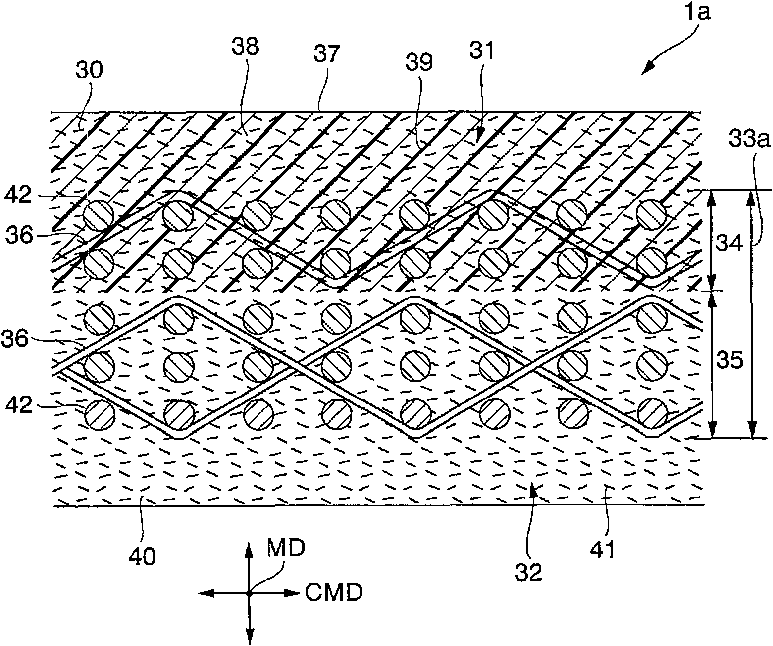
[0117] 1. Base fabric 33a:
[0118] ·The upper fabric (first fabric 34) has a warp double-layer structure (a warp composed of nylon monofilament yarns and a weft composed of nylon monofilament yarns), and has 400g / m 2 Unit weight.
[0119] The lower fabric (the second fabric 35) has a warp three-layer structure (a warp composed of nylon monofilament spun yarn and a weft composed of PET single yarn), and has 600g / m 2 Unit weight.
[0120] 2. Cotton batting layer: the same as Example 1 of the invention.
[0121] 3. Pouring of high polymer elastomer 39: the same as Example 1 of the invention.
[0122] 4. Dimensional changes caused by the experimental device:
[0123] ·Dimensional changes after the experiment: moving direction (extended by 1.2%), weft direction (extended by 0.6%)
example 3
[0125] 1. Base fabric 33b:
[0126] ·The upper fabric (first fabric 34) has a 1 / 1 plain weave structure (warp made of nylon multifilament yarn and weft made of PET single yarn), and has 200g / m 2 Unit weight.
[0127] The lower fabric (the second fabric 35) has a warp three-layer structure (a warp composed of nylon monofilament spun yarn and a weft composed of PET single yarn), and has 600g / m 2 Unit weight.
[0128] 2. Cotton batting layer: the same as Example 1 of the invention.
[0129] 3. Pouring of high polymer elastomer 39: the same as in Example 1 of the invention.
[0130] 4. Dimensional changes caused by the experimental device:
[0131] · Dimensional changes after the experiment: moving direction (extended by 1.2%), weft direction (extended by 0.4%)
[0132] (Comparative example 1)
[0133] 1. Base fabric:
[0134] ·The upper fabric (the fabric on the wet paper side) has a 1 / 1 plain weave structure (warp made of nylon multifilament yarn and weft made of nylon single yarn),...
PUM
 Abstract
Description
Claims
Application Information
 - R&D
- Intellectual Property
- Life Sciences
- Materials
- Tech Scout
- Unparalleled Data Quality
- Higher Quality Content
- 60% Fewer Hallucinations
Browse by: Latest US Patents, China's latest patents, Technical Efficacy Thesaurus, Application Domain, Technology Topic, Popular Technical Reports.
© 2025 PatSnap. All rights reserved.Legal|Privacy policy|Modern Slavery Act Transparency Statement|Sitemap|About US| Contact US: help@patsnap.com


